XA1E-BV313-R IDEC, XA1E-BV313-R Datasheet - Page 5
XA1E-BV313-R
Manufacturer Part Number
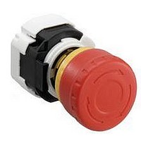
XA1E-BV313-R
Description
SWITCH, EMERGENCY STOP, 1NO/3NC, 250VAC
Manufacturer
IDEC
Datasheet
1.XA1E-BV311-R.pdf
(6 pages)
Specifications of XA1E-BV313-R
Contact Configuration
4PST-3NC / 1NO
Switch Operation
Pushlock Reset/Push-Pull
Contact Voltage Ac Nom
250V
Contact Voltage Dc Nom
250V
Contact Current Max
3A
Actuator Style
Mushroom
Lead Free Status / RoHS Status
Lead free / RoHS Compliant


Switches & Pilot Devices
Removing the Contact Block
First unlock the operator button. While pushing up the white bayonet ring, using
a small screwdriver (width: 2.5 to 3 mm) if necessary, turn the contact block
counterclockwise and pull out. Do not exert excessive force when using a
screwdriver, otherwise the bayonet ring may be damaged.
Notes for Removing the Contact Block
1. When the contact block is removed, the monitor contact (NO contact) is
2. While removing the contact block, do not exert excessive force, otherwise the
Panel Mounting
Remove the locking ring from the operator and check that the rubber gasket is in
place. Insert the operator from panel front into the panel hole. Face the side with
the anti-rotation tab on the operator upward, and tighten the locking ring.
Notes for Panel Mounting
To mount XA emergency stop switches onto a panel, tighten the locking ring to
a tightening torque of 0.88 N·m maximum using ring wrench MT-001. Do not use
pliers. Do not exert excessive force, otherwise the locking ring may be damaged.
Installing the Contact Block
First turn the bayonet ring to the unlocked position.
closed.
switch may be damaged.
Rubber Gasket
k Turn counterclockwise
Unlocked
Bayonet Ring
Operator Unit
Locking Ring
Bayonet Ring
j Push
Anti-rotation Tab
USA: 800-262-IDEC
Locked
Operating Instructions
Canada: 888-317-IDEC
Align the small p marking on the edge of the operator base with the TOP mark-
ing on the contact block. Press the contact block onto the operator and turn the
contact block clockwise until the bayonet ring clicks.
Notes for Installing the Contact Block
Check that the contact block is securely installed on the operator. When the
emergency stop switch is properly assembled, the bayonet ring is in place as
shown below.
Removing the LED Unit
Pull out the LED unit while squeezing the latches on the LED unit using the LED
unit removal tool (MT-101).
Installing the LED Unit
Align the top of the LED unit with the TOP marking on the contact block. Push the
LED unit into the contact block.
p marking
TOP side
j Press
16mm XA E-Stops
TOP marking
Squeeze the LED unit on the
latches and pull out.
TOP marking (contact block)
TOP side
Latches
k Turn
455
Related parts for XA1E-BV313-R
Image
Part Number
Description
Manufacturer
Datasheet
Request
R

Part Number:
Description:
SWITCH, EMERGENCY STOP, 1NO/1NC, 250VAC
Manufacturer:
IDEC
Datasheet:

Part Number:
Description:
SWITCH, EMERGENCY STOP, 1NC, 250VAC
Manufacturer:
IDEC
Datasheet:
Part Number:
Description:
SWITCH, EMERGENCY STOP, 1NC, 250VAC
Manufacturer:
IDEC
Datasheet:
Part Number:
Description:
SWITCH, EMERGENCY STOP, 2NC, 250VAC
Manufacturer:
IDEC
Datasheet:
Part Number:
Description:
SWITCH, EMERGENCY STOP, 2NC, 250VAC
Manufacturer:
IDEC
Datasheet:

Part Number:
Description:
SWITCH, EMERGENCY STOP, 2NC, 250VAC
Manufacturer:
IDEC
Datasheet:
Part Number:
Description:
SWITCH, EMERGENCY STOP, 1NO/1NC, 250VAC
Manufacturer:
IDEC
Datasheet:

Part Number:
Description:
SWITCH, EMERGENCY STOP, 1NO/1NC, 250VAC
Manufacturer:
IDEC
Datasheet:
Part Number:
Description:
SWITCH, EMERGENCY STOP, 3NC/1NO, 250VAC
Manufacturer:
IDEC
Datasheet:

Part Number:
Description:
SWITCH, EMERGENCY STOP, 1NC, 250VAC
Manufacturer:
IDEC
Datasheet:

Part Number:
Description:
INDICATOR INCANDESCENT LAMP, GREEN
Manufacturer:
IDEC
Datasheet:

Part Number:
Description:
LAMP, INDICATOR, INCAND, AMB
Manufacturer:
IDEC
Datasheet:
Part Number:
Description:
LAMP, INDICATOR, INCAND, GRN
Manufacturer:
IDEC
Datasheet:
Part Number:
Description:
LAMP, INDICATOR, INCAND, GRN
Manufacturer:
IDEC
Datasheet:
Part Number:
Description:
LAMP, INDICATOR, INCANDESCENT, RED
Manufacturer:
IDEC
Datasheet: