94.73SMA FINDER, 94.73SMA Datasheet
94.73SMA
Specifications of 94.73SMA


Related parts for 94.73SMA


94.73SMA Summary of contents
Page 1
Features Printed circuit mount, general purpose 2, 3 & 4 Pole relays 55. Pole 10 A 55. Pole 10 A 55. Pole coils & DC coils • Cadmium Free contacts (preferred ...
Page 2
Features Plug-in mount, general purpose 2, 3 & 4 Pole relays 55. Pole 10 A 55. Pole 10 A 55. Pole 7 A Lockable test button and mechanical flag • indicator as standard on ...
Page 3
... A1/13) Lockable test button and mechanical flag indicator (0040) The dual-purpose Finder test button can be used in two ways: Case 1) The plastic pip (located directly above the test button) remains intact. In this case, when the test button is pushed, the contacts operate. When the test button is released the contacts return to their former state ...
Page 4
Technical data Insulation Insulation according to EN 61810-1 ed. 2 Insulation between coil and contacts (1.2/50 µs) Dielectric strength between open contacts Dielectric strength between adjacent contact Conducted disturbance immunity Burst (5...50)ns, 5 kHz Surge (1.2/50 ...
Page 5
Coil specifications DC coil data Nominal Coil Operating range voltage code min max 9.006 4.8 6.6 12 9.012 9.6 13.2 9.024 24 19.2 26.4 48 9.048 38.4 52.8 60 9.060 48 66 ...
Page 6
Module Socket 99.02 94.02 94.03 94.04 94.04 See page 69 Module Socket 99.80 94.54.1 55.32 Screwless terminal socket 94.54.1 See page 70 Module Socket 55 99.01 94.72 94.73 94.74 94.74 See page 71 Module Socket 99.01 94.82 94.82 See page ...
Page 7
Screw terminal (Box clamp) socket panel rail mount Colour For relay type Accessories Metal retaining clip 94.04 Plastic retaining and release clip Approvals (supplied with socket - packaging code SPA) (according to type): 6-way jumper link Identification ...
Page 8
Screwless terminal socket 35 mm rail (EN 50022) mount 094.92 For relay type Accessories Metal retaining clip Plastic retaining and release clip 94.54.1 Modules (see table below) Approvals Sheet of marker tags for retaining and release clip 094.92 (according to ...
Page 9
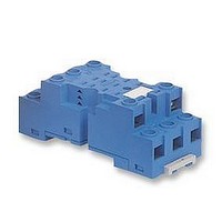
Screw terminal (Plate clamp) socket panel rail mount 94.72 Colour For relay type Accessories Metal retaining clip (supplied with socket - packaging code SMA) 94.74 Modules (see table below) Approvals Screw terminal (Plate clamp) socket: panel or ...
Page 10
Screw terminal (Box clamp) socket panel rail mount Colour For relay type Accessories Metal retaining clip (supplied with socket - packaging code SMA) 94.84.3 Plastic retaining and release clip Approvals 6-way jumper link (according to type): ...
Page 11
Rated values 094.06 0.75 26.25 27 99.80 coil indication and EMC suppression modules for 94.82.3, 94.84.3 and 94.92.3, 94.94.3 sockets See technical data pages 247/248 Diode (+A1, standard polarity) LED LED 99.80 ...
Page 12
Panel mount solder socket 1 mm thick panel Colour For relay type Accessories Metal retaining clip (supplied with socket - packaging code SMA) 94.22 Technical data Approvals Rated values (according to type): Dielectric strength Ambient temperature 21.8 55 Panel mount ...