41.52.9.012.0010 FINDER, 41.52.9.012.0010 Datasheet - Page 3
41.52.9.012.0010
Manufacturer Part Number
41.52.9.012.0010
Description
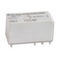
RELAY, PCB, DPCO, 12VDC
Manufacturer
FINDER
Datasheet
1.41.52.9.024.0010.pdf
(4 pages)
Specifications of 41.52.9.012.0010
Relay Type
General Purpose
Coil Voltage Vdc Nom
12V
Contact Current Max
15A
Contact Voltage Ac Nom
250V
Coil Resistance
360ohm
Coil Type
DC Coil
Coil Current
33.3mA
Nom Operating Power
400mW
Relay
RoHS Compliant
Contact Configuration
DPCO
Rohs Compliant
Yes


F 41 - Electrical life (AC) v contact current
Contact specification
H 41- Maximum DC1 breaking capacity
• When switching a resistive load (DC1) having voltage and current
• In the case of DC13 loads, the connection of a diode in parallel with
Coil specifications
DC coil data
Nominal
values under the curve, an electrical life of ≥ 100·10
the load will permit a similar electrical life as for a DC1 load.
Note: the release time for the load will be increased.
voltage
110
U
V
12
24
48
60
N
Types 41.31/61
10
10
10
10
0.2
0.1
20
10
7
6
5
4
6
4
2
1
20
0
41.61 limit current
9.012
9.024
9.048
9.060
9.110
41.31 limit current
code
Coil
41.52 limit current
limit for 41.31
60
4
single contact
Operating range
U
16.8
33.6
42
77
V
min
8.4
100
Resistive load - cosϕ = 1
Inductive load - cosϕ = 0.4
DC voltage (V)
41.52 - 2 contacts in series
8
165
U
18
36
72
90
max
V
140
Resistance Rated coil
24,200
12
1,440
5,760
9,000
Ω
180
R
3
360
can be expected.
41 Series - Low profile PCB relays 8 - 12 - 16 A
consumption
I at U
220
33.3
19.7
mA
16
(A)
8.3
6.6
4.5
N
F 41 - Electrical life (AC) v contact current
R 41 - DC coil operating range v ambient temperature
1 - Max. permitted coil voltage.
2 - Min. pick-up voltage with coil at ambient temperature.
U
U
Type 41.52
N
10
10
10
10
2.5
2.0
1.5
1.0
0.5
7
6
5
4
0
-20
0
4
Resistive load - cosϕ = 1
Inductive load - cosϕ = 0.4
20
8
40
2
12
60
1
(°C)
80
16
(A)
35
41
Related parts for 41.52.9.012.0010
Image
Part Number
Description
Manufacturer
Datasheet
Request
R

Part Number:
Description:
JUMPER LINK, 20WAY
Manufacturer:
FINDER
Datasheet:


Part Number:
Description:
INTERFACE RELAY, SPDT-CO, 24VAC/DC
Manufacturer:
FINDER
Datasheet:
Part Number:
Description:
INTERFACE RELAY, SPDT-CO, 24VDC
Manufacturer:
FINDER
Datasheet:

Part Number:
Description:
RELAY, SCREW TERM, 6A, 12VAC/DC
Manufacturer:
FINDER
Datasheet:
Part Number:
Description:
RELAY, SCREW TERM, 6A, 48VAC/DC
Manufacturer:
FINDER
Datasheet:
Part Number:
Description:
RELAY, SCREW TERM, 6A, 125VAC/DC
Manufacturer:
FINDER
Datasheet:
Part Number:
Description:
RELAY, SCREW TERM, 6A, 240VAC/DC
Manufacturer:
FINDER
Datasheet:
Part Number:
Description:
RELAY, SCREW TERM, 6A, 6VDC
Manufacturer:
FINDER
Datasheet:
Part Number:
Description:
RELAY, SCREW TERM, 6A, 12VDC
Manufacturer:
FINDER
Datasheet:
Part Number:
Description:
RELAY, SCRW TER, DPDT, 8A, 24VAC/DC
Manufacturer:
FINDER
Datasheet:
Part Number:
Description:
RELAY, SCREW TERM, DPDT, 8A, 12VDC
Manufacturer:
FINDER
Datasheet:
Part Number:
Description:
RELAY, SCREW TERM, DPDT, 8A, 24VDC
Manufacturer:
FINDER
Datasheet:

Part Number:
Description:
RELAY, SCREWLESS, 6A, 24VDC
Manufacturer:
FINDER
Datasheet: