G6L-1F 12DC Omron, G6L-1F 12DC Datasheet - Page 2
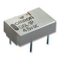
G6L-1F 12DC
Manufacturer Part Number
G6L-1F 12DC
Description
RELAY, SMD, SPNO, 12VDC
Manufacturer
Omron
Datasheet
1.G6L-1F_24DC.pdf
(8 pages)
Specifications of G6L-1F 12DC
Coil Type
DC Coil, Monostable
Contact Current Max
1A
Contact Voltage Ac Nom
125V
Contact Voltage Dc Nom
24V
Coil Voltage Vdc Nom
12V
Coil Current
15mA
Coil Resistance
800ohm
Relay Mounting
PC Board
Contact Configuration
SPNO
Rohs Compliant
Yes
Lead Free Status / RoHS Status
Lead free / RoHS Compliant


G6L
Specifications
Single-side Stable Relays (G6L-1P, G6L-1F)
Note:
Note:
2
ItemLoad
Contact mechanism
Rated load
Rated carry current
Max. switching voltage
Max. switching current
Rated voltage
Rated current
Coil resistance
Must operate voltage
Must release voltage
Maximum voltage
Power consumption
Item
Contact resistance (See note 1.)
Operating time (See note 2.)
Release time (See note 2.)
Insulation resistance (See note 3.)
Dielectric strength
Impulse withstand
voltage
Vibration resistance
Shock resistance
Life expectancy
Failure rate (P level) (See note 4.)
Ambient temperature
Ambient humidity
Weight
Contact Ratings
Coil Ratings
Characteristics
1. The rated current and coil resistance are measured at a coil temperature of 23°C with a tolerance of ±10%.
2. The operating characteristics are measured at a coil temperature of 23°C.
3. The maximum voltage is the highest voltage that can be imposed on the relay coil.
1. The contact resistance was measured with 10 mA at 1 VDC with a fall-of-potential method.
2. Values in parentheses are actual values.
3. The insulation resistance was measured with a 500-VDC Megger Tester applied to the same parts as those used for checking
4. This value was measured at a switching frequency of 120 operations/min. This value may vary, depending on switching
5. The above values are initial values.
the dielectric strength.
frequency, operating conditions, expected reliability level of the relay, etc. It is always recommended to double-check relay
suitability under actual load conditions.
Coil and contacts
Contacts of same
polarity
Coil and contacts
Destruction
Malfunction
Destruction
Malfunction
Mechanical
Electrical
Single crossbar
0.3 A at 125 VAC, 1 A at 24 VDC
1 A
125 VAC, 60 VDC
1 A
3 VDC
60.0 mA
50.0
75% max. of rated voltage
10% min. of rated voltage
150% of rated voltage
Approx. 180 mW
Classification
Model
Resistive load
100 m
5 ms max. (approx. 1.1 ms)
5 ms max. (approx. 0.4 ms)
1,000 M
1,000 VAC, 50/60 Hz for 1 min
750 VAC, 50/60 Hz for 1 min
1,500 VAC, 10
10 to 55 Hz, 1.65-mm single amplitude (3.3-mm double amplitude)
10 to 55 Hz, 1.65-mm single amplitude (3.3-mm double amplitude)
1,000 m/s
100 m/s
5,000,000 operations min. (at 36,000 operations/hour)
100,000 operations min. (with a rated load at 1,800 operations/hour)
1 mA at 5 VDC
Operating: -40°C to 70°C (with no icing or condensation)
Operating: 5% to 85%
Approx. 0.6 g
4.5 VDC
40.0 mA
112.5
2
max.
2
min. (at 500 VDC)
160 s
5 VDC
36.0 mA
139.0
Single-side Stable Relays
G6L-1P, G6L-1F
12 VDC
15.0 mA
800.0
24 VDC
9.6 mA
2,504.0
130% of rated
voltage
Approx. 230 mW
G6L
Related parts for G6L-1F 12DC
Image
Part Number
Description
Manufacturer
Datasheet
Request
R

Part Number:
Description:
LOW SIGNAL RELAY
Manufacturer:
Omron
Datasheet:

Part Number:
Description:
Low Signal Relays - PCB SMT TAPE AND REEL RELAY
Manufacturer:
Omron
Datasheet:
Part Number:
Description:
RELAY LOW SIGNAL SMD TR
Manufacturer:
Omron
Datasheet:
Part Number:
Description:
RELAY LOW SIGNAL SMD TR
Manufacturer:
Omron
Datasheet:

Part Number:
Description:
Low Signal Relays - PCB LO PROF SPST 3VDC
Manufacturer:
Omron
Datasheet:
Part Number:
Description:
Low Signal Relays - PCB LO PROF SPST 12VDC
Manufacturer:
Omron
Datasheet:
Part Number:
Description:
Low Signal Relays - PCB LO PROF SPST 5VDC
Manufacturer:
Omron
Datasheet:
Part Number:
Description:
Low Signal Relays - PCB 12VDC SPST-NO Low profile T and R
Manufacturer:
Omron
Datasheet:
Part Number:
Description:
RELAY TELCOM SPST 24V SMD
Manufacturer:
Omron
Datasheet:
Part Number:
Description:
SMT TAPE AND REEL RELAY
Manufacturer:
Omron
Datasheet:

Part Number:
Description:
G6S-2GLow Signal Relay
Manufacturer:
Omron Corporation
Datasheet: