G6L-1F 12DC Omron, G6L-1F 12DC Datasheet - Page 3
G6L-1F 12DC
Manufacturer Part Number
G6L-1F 12DC
Description
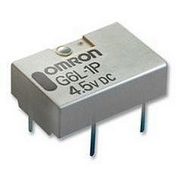
RELAY, SMD, SPNO, 12VDC
Manufacturer
Omron
Datasheet
1.G6L-1F_24DC.pdf
(8 pages)
Specifications of G6L-1F 12DC
Coil Type
DC Coil, Monostable
Contact Current Max
1A
Contact Voltage Ac Nom
125V
Contact Voltage Dc Nom
24V
Coil Voltage Vdc Nom
12V
Coil Current
15mA
Coil Resistance
800ohm
Relay Mounting
PC Board
Contact Configuration
SPNO
Rohs Compliant
Yes
Lead Free Status / RoHS Status
Lead free / RoHS Compliant


G6L
Engineering Data
Maximum Switching Capacity
Life Expectancy
Electrical Life Expectancy (with
Must Operate and Must Release
Voltage) (See note.)
100
1,000
0.7
0.5
0.3
0.1
500
300
100
10
80
60
40
20
7
5
3
1
50
30
10
0
10
5
3
1
0.1
0
Sample: G6L-1F
Number of Relays: 10
Test conditions: 1-A resistive load at
24-VDC with an operation rate of 50%
Switching frequency: 1,800 operations/h
DC resistive load
125-VAC resistive load
Must operate voltage
Must release voltage
Operating frequency ( 10
0.2
30
1
0.4
50 70 100
AC resistive load
10
0.6
Switching voltage (V)
24-VDC resistive load
Switching current (A)
0.8
300 500 7001,000
3
100
operations)
max.
min.
max.
min.
1
1,000
1.2
Ambient Temperature vs.
Maximum Voltage
Note: "Maximum voltage" is the maximum voltage that can
Ambient Temperature vs. Must
Operate or Must Release Voltage
Electrical Life Expectancy
(Contact Resistance) (See note.)
100
1,000
250
200
150
100
90
80
70
60
50
40
30
20
10
50
500
300
100
0
60
0
50
30
10
40
be applied to the Relay coil.
0.1
Contact resistance
Sample: G6L-1F
Number of Relays: 10
Test conditions: 1-A resistive load at
24-VDC with an operation rate of 50%
Switching frequency: 1,800 operations/h
40
20
Operating frequency ( 10
24 VDC
20
1
0
3 to 12 VDC
0
Ambient temperature (˚C)
Ambient temperature (˚C)
20
10
20
Max. estimated value
Must operate voltage
Must release voltage
40
40
100
3
operations)
max.
min.
NO contact
60
60
max.
avg.
min.
max.
avg.
min.
1,000
80
80
Ambient Temperature vs.
Switching Current
Shock Malfunction
Contact Reliability Test (Contact
Resistance) (See note.)
Shock direction
Conditions: Shock is applied in ±X, ±Y, and ±Z
directions three times each with and without energizing
the Relays to check the number of contact
malfunctions.
Note: The tests were conducted at an ambient
Y
Y'
1,000
X
1,000
1,000
1.2
0.8
0.6
0.4
0.2
500
300
100
50
30
10
1
0
Z'
X
40
1
Sample: G6L-1F
Number of Relays: 10
Test conditions: 1-A resistive load at
24-VDC with an operation rate of 50%
Switching frequency: 1,800 operations/h
temperature of 23ºC.
X'
Z
Z'
Operating frequency ( 10
20
10
1,000
200
400
600
800
0
Y
Y'
1,000
800
600
400
200
Ambient temperature (˚C)
20
100
Unit: m/s
Sample: G6L-1F
Number of Relays: 10
Energized
40
2
1,000
3
1,000
1,000
operations)
NO contact
Z
X'
60
G6L
10,000
max.
min.
80
3
Related parts for G6L-1F 12DC
Image
Part Number
Description
Manufacturer
Datasheet
Request
R

Part Number:
Description:
LOW SIGNAL RELAY
Manufacturer:
Omron
Datasheet:

Part Number:
Description:
Low Signal Relays - PCB SMT TAPE AND REEL RELAY
Manufacturer:
Omron
Datasheet:
Part Number:
Description:
RELAY LOW SIGNAL SMD TR
Manufacturer:
Omron
Datasheet:
Part Number:
Description:
RELAY LOW SIGNAL SMD TR
Manufacturer:
Omron
Datasheet:

Part Number:
Description:
Low Signal Relays - PCB LO PROF SPST 3VDC
Manufacturer:
Omron
Datasheet:
Part Number:
Description:
Low Signal Relays - PCB LO PROF SPST 12VDC
Manufacturer:
Omron
Datasheet:
Part Number:
Description:
Low Signal Relays - PCB LO PROF SPST 5VDC
Manufacturer:
Omron
Datasheet:
Part Number:
Description:
Low Signal Relays - PCB 12VDC SPST-NO Low profile T and R
Manufacturer:
Omron
Datasheet:
Part Number:
Description:
RELAY TELCOM SPST 24V SMD
Manufacturer:
Omron
Datasheet:
Part Number:
Description:
SMT TAPE AND REEL RELAY
Manufacturer:
Omron
Datasheet:

Part Number:
Description:
G6S-2GLow Signal Relay
Manufacturer:
Omron Corporation
Datasheet: