RE8TA31BU TELEMECANIQUE, RE8TA31BU Datasheet - Page 10
RE8TA31BU
Manufacturer Part Number
RE8TA31BU
Description
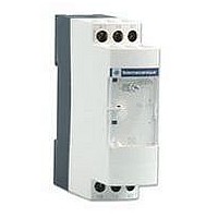
TIMER, ON-DELAY, 3-30S
Manufacturer
TELEMECANIQUE
Datasheet
1.RE8RA21FU.pdf
(12 pages)
Specifications of RE8TA31BU
Contact Configuration
SPCO
Nom Input Voltage
240VAC
Delay Time Range
3s To 30s
Relay Mounting
DIN Rail
Coil Voltage Vac Nom
240V
Contact Current Ac Max
8A
Contact Current Dc Max
8A


3
– KM2
Characteristics :
pages 2/36 and 2/37
References :
page 2/40
Dimensions :
page 2/42
Schemes
Terminal blocks
RE8-PE
Recommended application schemes
Pulse on energisation relays
RE8-PE, PT
Timing relays for star-delta starters
RE8-YG, RE8-YA
Note: Correct operation of the star-delta starter associated with the RE8-YG is only possible if the wiring scheme is strictly complied with.
Setting-up
1
– Q1
A1
18
24
15
16
B1
B1
A2
2
– KM3
A1
1
2
10 s
A2
x. %
RE8-PD
– KM1
A1
18
Y
– Rth
Zelio Time - timing relays
Relay output, width 22.5 mm, optimum
Pulse on energisation relays, relays for star-delta starters
Schemes, setting-up
15
16
Y1
A2
RE8-YG
(1) K1T: RE8-YGi1iiTQ
1
2
3
Adjustment of the time delay
- The maximum value of the timing range is printed on the product 2.
Example: RE8-PE11BUTQ; maximum time delay: 10 s.
- Time required 2.4 s; using potentiometer
value
– Rth
– S2
– S1
– KM1
Potentiometer for fine adjustment of the time delay, graduated in % of range max. setting 2.
Marking of maximum time delay value.
LEDs, depending on the models :
- Yellow LED: illuminates when the output relay is energised,
- Green LED: illuminates when the RE8 is energised.
– KM2
– KM3
1
= –––––– = –––––––– = 24
RE8-PT
RE8-PD
Y
+
–
t x 100
A1
18
– FU1
– K1T
2
(1)
15
16
– KM1
2.4 x 100
– KM1
A2
B1
A2
10
A1
Y1
– K1T
16
– KM3
– KM2
15
(1)
Start
L
– KM1
1
RE8-YA
– KM2
set the value of the time delay required as a % of value 2:
A1
28
15
16
RE8-YA
(1) K1T: RE8-YA32iiTQ
– Rth
– S2
25
A2
– S1
– K1T
– KM1
– KM3
Y
– FU1
– K1T
(1)
– KM1
Te
RE8-YG
L
A1
18
– K1T
– KM2
– KM2
– KM1
15
16
B1
A2
– KM3
2/41
2
Related parts for RE8TA31BU
Image
Part Number
Description
Manufacturer
Datasheet
Request
R

Part Number:
Description:
Control Contactor
Manufacturer:
TELEMECANIQUE
Datasheet:

Part Number:
Description:
Control Contactor
Manufacturer:
TELEMECANIQUE
Datasheet:

Part Number:
Description:
Contactor
Manufacturer:
TELEMECANIQUE
Datasheet:

Part Number:
Description:
Contactor
Manufacturer:
TELEMECANIQUE
Datasheet:
Part Number:
Description:
Control Contactor
Manufacturer:
TELEMECANIQUE
Datasheet:

Part Number:
Description:
CONTACTOR, 2NO/2NC, 9A, 230VAC
Manufacturer:
TELEMECANIQUE
Datasheet:

Part Number:
Description:
Contactor
Manufacturer:
TELEMECANIQUE
Datasheet:

Part Number:
Description:
CONTACTOR, 4KW, 400VAC
Manufacturer:
TELEMECANIQUE
Datasheet:

Part Number:
Description:
CONTACTOR, 5.5KW, 230VAC
Manufacturer:
TELEMECANIQUE
Datasheet:
Part Number:
Description:
CONTACTOR, 5.5KW, 400VAC
Manufacturer:
TELEMECANIQUE
Datasheet:

Part Number:
Description:
PILOT LIGHT HEAD, WHITE
Manufacturer:
TELEMECANIQUE
Datasheet:

Part Number:
Description:
LENS HEAD, BA 9S
Manufacturer:
TELEMECANIQUE
Datasheet:
Part Number:
Description:
LENS HEAD, BA 9S
Manufacturer:
TELEMECANIQUE
Datasheet:

Part Number:
Description:
LED BODY, 24V
Manufacturer:
TELEMECANIQUE
Datasheet:
Part Number:
Description:
LED BODY, 48V
Manufacturer:
TELEMECANIQUE
Datasheet: