RE8TA31BU TELEMECANIQUE, RE8TA31BU Datasheet - Page 6
RE8TA31BU
Manufacturer Part Number
RE8TA31BU
Description
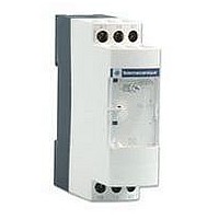
TIMER, ON-DELAY, 3-30S
Manufacturer
TELEMECANIQUE
Datasheet
1.RE8RA21FU.pdf
(12 pages)
Specifications of RE8TA31BU
Contact Configuration
SPCO
Nom Input Voltage
240VAC
Delay Time Range
3s To 30s
Relay Mounting
DIN Rail
Coil Voltage Vac Nom
240V
Contact Current Ac Max
8A
Contact Current Dc Max
8A


References :
pages 2/38 and 2/40
Dimensions :
page 2/42
Schemes, setting-up :
pages 2/39, 2/41 and 2/43
Time delay characteristics
Setting accuracy
Repeat accuracy
Influence of voltage
Influence of temperature
Immunity to
micro-breaks
Minimum control pulse
Reset time
Output circuit characteristics
Maximum switching voltage
Mechanical durability
Current limit Ith
Rated operational limits at 70 C
Conforming to IEC 60947-5-1/1991
and VDE 0660
Minimum switching capacity
Contact material
Remote control input characteristics
Signal delivered by
control input Y1
this input and the power supply
a.c. load
Curve 1
Electrical durability of contacts on resistive
load in millions of operating cycles
A
Example:
An LC1-F185 contactor supplied with 115 V/50 Hz for a consumption of 55 VA or a current
consumption equal to 0.1 A and cos
For 0.1 A, curve 1 indicates a durability of approximately 1.5 million operating cycles.
As the load is inductive, it is necessary to apply a reduction coefficient k to this number of
cycles, as indicated by curve 2.
For cos
The electrical durability therefore becomes:
1.5 10
0,01
0,1
10
RE8-RBiiBUTQ
1
No galvanic insulation between
0
6
operating cycles x 0.6 = 900 000 operating cycles
1
= 0.3: k = 0.6
2
3
4
A
Current broken in A
5
6
7
= 0.3
Zelio Time - timing relays
Relay output, width 22.5 mm, optimum
General characteristics
As % of the full scale value
In the voltage range, 0.9…1.1 Un
In millions of operating cycles
AC-15
DC-13
No-load voltage
Switching current
Maximum distance
Compatibility
8
Curve 2
Reduction factor k for inductive loads
(applies to values taken from the
durability curve opposite)
0,9
0,8
0,7
0,6
0,5
0,4
0,3
1
1
0,8
0,6 0,5
Power factor on breaking (cos )
(continued)
0,4
ms
ms
A
A
mA
m
ms
V
A
0,3
< 1 %
< 2.5 %
< 0.2 %/ C
3
26 (except RE8-YG: 60)
50
z 250
20
8
24 V
3
2
12 V/10 mA
Nickel Silver 90/10
Supply voltage
< 10
50
a 2-wire sensors with leakage current < 1 mA
20 %
0,2
A
1
2
3
d.c. load
Load limit curve
+
–
RE8-RBiiBUTQ
L/R = 20 ms
L/R with load protection diode
Resistive load
300
200
100
RE8
115 V
3
0.2
50
40
30
20
10
K
0,1
0,2
1
2
0,5
3
250 V
3
0.1
1
Te
2
A
5
Current in A
10
20
2/37
2
Related parts for RE8TA31BU
Image
Part Number
Description
Manufacturer
Datasheet
Request
R

Part Number:
Description:
Control Contactor
Manufacturer:
TELEMECANIQUE
Datasheet:

Part Number:
Description:
Control Contactor
Manufacturer:
TELEMECANIQUE
Datasheet:

Part Number:
Description:
Contactor
Manufacturer:
TELEMECANIQUE
Datasheet:

Part Number:
Description:
Contactor
Manufacturer:
TELEMECANIQUE
Datasheet:
Part Number:
Description:
Control Contactor
Manufacturer:
TELEMECANIQUE
Datasheet:

Part Number:
Description:
CONTACTOR, 2NO/2NC, 9A, 230VAC
Manufacturer:
TELEMECANIQUE
Datasheet:

Part Number:
Description:
Contactor
Manufacturer:
TELEMECANIQUE
Datasheet:

Part Number:
Description:
CONTACTOR, 4KW, 400VAC
Manufacturer:
TELEMECANIQUE
Datasheet:

Part Number:
Description:
CONTACTOR, 5.5KW, 230VAC
Manufacturer:
TELEMECANIQUE
Datasheet:
Part Number:
Description:
CONTACTOR, 5.5KW, 400VAC
Manufacturer:
TELEMECANIQUE
Datasheet:

Part Number:
Description:
PILOT LIGHT HEAD, WHITE
Manufacturer:
TELEMECANIQUE
Datasheet:

Part Number:
Description:
LENS HEAD, BA 9S
Manufacturer:
TELEMECANIQUE
Datasheet:
Part Number:
Description:
LENS HEAD, BA 9S
Manufacturer:
TELEMECANIQUE
Datasheet:

Part Number:
Description:
LED BODY, 24V
Manufacturer:
TELEMECANIQUE
Datasheet:
Part Number:
Description:
LED BODY, 48V
Manufacturer:
TELEMECANIQUE
Datasheet: