ASF1400 SENSIRION, ASF1400 Datasheet - Page 5
ASF1400
Manufacturer Part Number
ASF1400
Description
SENSOR, MASS FLOW
Manufacturer
SENSIRION
Datasheet
1.ASF1400.pdf
(11 pages)
Specifications of ASF1400
Pressure Max
120Pa
Supply Voltage Range Dc
7V To 18V
Accuracy
± 1%
Air Mass Flow Range
-400sccm To 400sccm
Svhc
No SVHC (15-Dec-2010)
Connection Size
5mm
Measuring Range
.015 To 400 Sscm
Supply Voltage Dc
RoHS Compliant
Response Time
142ms
Rohs Compliant
Yes


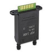
ASF1400 Bidirectional Mass Flow Meter
2
Figure 6: ASF1400 pin out.
GND and VDD (Power Supply)
The ASF1400 requires a voltage supply of between 7
V and 18 V. Since this voltage is internally regulated,
there are no stringent requirements as far as ripple
and stability are concerned.
2.1 Connector
You need a EDAC 395-010-520-102 connector to
connect the sensor. Please check the EDAC
homepage for details (http:// www.edac.net).
2.2 RS-232 Interface
All configurations (see also Section 3) for the
ASF1400 can be set using its RS-232 interface). To
communicate with the ASF1400 via RS-232 the
following pins are required:
RxD
TxD
GND
The RS-232 of the ASF1400 is configured as follows:
Baudrate
Data Bits
Stop Bits
Parity
Protocol
With these settings, the ASF1400 device can be
connected to any PC or PDA equipped with terminal
software.
The measurement values are provided as a signed
floating point number together with the corresponding
unit (sccm for mass flow, C for temperature). In case
of an overflow, the output shows oF.
2.3 Serial Peripheral Interface (SPI)
To make measurement data available also for smaller
systems or to cascade several ASF1400 devices, the
ASF1400 provides a uni-directional SPI interface.
The configuration of the ASF1400 (as described in
Section 3) has to be done using the RS-232 port. The
SPI interface provides the measurement data as a 24
www.sensirion.com
Pins and Digital Interface
(Receiving Data Line)
(Transmitting Data Line)
(Ground)
9600
8
1
none
none
Version 2.1
bit signed integer, where bit 0…22 defines the value
and bit 23 the sign (0 indicates the positive, and a 1
the negative sign). The 24 bits are transmitted in 3
blocks, each consists of one byte. The MSB (bit 23) is
sent first.
Since the calibrated mass flow and temperature
output values of the ASF1400 sensor have floating
point precision, the transmitted integer data is
multiplied with an SPI factor. This factor is 100.
Example: a received flow SPI value of +1234
corresponds to a flow of 12.34 sccm. Figure 7 shows
the internal setup of the SPI inter-face lines and
Figure 8 an example of cascading four ASF1400
devices using a single microcontroller.
Note: With each additional sensor the capacitive load
will increase, causing an increase of the output
fall/rise time and an output signal deterioration.
PIN 3
PIN 4
PIN 5
PIN 6
Figure 7: Internal ASF1400 SPI hardware.
Figure 8: Cascading four ASF1400 devices using the
SPI interface.
SERIAL CLOCK (SCK)
SPI
CHIP
SELECTION
MASTER MCU
DATA IN (MISO)
MOSI
MISO
SCK
/CS
/CS0
/CS1
/CS2
/CS3
560
560
560
560
47 pF
GND
GND
+5 V
50 K
MICRO-
CONTROLLER
SCK
MOSI
/CS
SCK
MOSI
/CS
ASF 1400
SCK
MOSI
/CS
SCK
MOSI
/CS
5/11
Related parts for ASF1400
Image
Part Number
Description
Manufacturer
Datasheet
Request
R


Part Number:
Description:
MODULE SENSOR TEMP+HUMIDITY
Manufacturer:
Parallax Inc
Datasheet:

Part Number:
Description:
Humidity Sensor Filter Cap
Manufacturer:
SENSIRION
Datasheet:

Part Number:
Description:
Sensor Evaluation Kit
Manufacturer:
SENSIRION
Datasheet:

Part Number:
Description:
Sensor Evaluation Kit
Manufacturer:
SENSIRION
Datasheet:
Part Number:
Description:
Sensor Evaluation Kit
Manufacturer:
SENSIRION
Datasheet:
Part Number:
Description:
Sensor Evaluation Kit
Manufacturer:
SENSIRION
Datasheet:

