SM912LV BANNER ENGINEERING, SM912LV Datasheet - Page 8
SM912LV
Manufacturer Part Number
SM912LV
Description
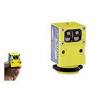
Photoelectric Sensor
Manufacturer
BANNER ENGINEERING
Datasheet
1.SM912LV.pdf
(20 pages)
Specifications of SM912LV
Output Current
250mA
Sensor Output
NPN/PNP
Supply Voltage Range Dc
10V To 30V
Sensing Range Max
9m
Sensor Housing
Rectangular
Switch Terminals
Cable
Sensor Input
Optical
Sensing Mode
Retroreflective


8
Hookup Diagrams for dc SM912 Series Sensors
VALU-BEAM 912 Series Sensors
Hookup to dc Relay or
Solenoid
The diagram below shows hookup of a dc VALU-
BEAM to a dc load using the sensor's sinking
output, which is rated at 250mA maximum.
The BLACK
wire is not
used.
Hookup to Programmable Controller
(sinking output)
Hookup to B Series Logic
This diagram shows hookup of a dc VALU-BEAM to a programmable
controller requiring a current sink, using the sensor's sinking output. The
BLACK wire
is not used.
Hookup to MAXI-AMP Logic Module
The current sinking output(s) of VALU-BEAM sen-
sors may be connected directly to the input of CL Series
MAXI-AMP modules. A MAXI-AMP which is pow-
ered by ac voltage offers a dc supply with the capacity
to power one VALU-
BEAM sensor (see
hookup diagram).
When emitter/receiver
pairs are used, the
emitter should be pow-
ered from a separate
power source.
Hookup shown is
typical for all
inputs.
+15V dc
7
8
1
2
7
8
1
2
120 Vac
B Series
Module
(using sinking output)
6
5
4
3
6
5
4
3
LOAD
WHITE
BROWN
BLUE
BLACK wire
is not used
BLACK
BROWN
WHITE
10 - 30V dc
BLACK wire
is not used
BLACK
BLACK
BLUE
CL3RA
CL3RB
CL5RA
CL5RB
The current sinking output (white
wire) of the VALU-BEAM is shown
connected to the input (pin 5) of a B
Series module. It may be connected
to the auxiliary input (pin 3) if de-
sired. (See description of module
for function of aux. input). Any B
Series module may be used. Ban-
ner PLUG LOGIC modules may
also be used (contact the factory for
further information).
(MRB chassis)
WHITE
(sinking output)
BLUE
(common)
BROWN
+10 - 30V dc
BROWN
WHITE
BLUE
The diagram below shows hookup of a dc VALU-
BEAM to a dc load using the sensor's sourcing
output, which is rated at 250mA maximum.
The WHITE
wire is not
used.
Hookup to dc Relay or
Solenoid
Hookup shown is
typical for all inputs
BLACK wire
is not used
dc com
dc+
1
2
3
4
5
6
7
8
N
P
U
T
S
BLACK
I
g.
P
o
C
l.
r
t
r
(using sourcing output)
BROWN
WHITE
Hookup to Programmable Controller
(sourcing output)
This diagram shows hookup of a dc VALU-BEAM to a programmable
controller requiring a current source, using the sensor's sourcing output. The
WHITE wire is not used.
10 - 30V dc
Hookup to MICRO-AMP Logic
Emitter Hookup
(ac or dc power)
The current sinking (white) output of the VALU-BEAM is shown con-
nected to the primary input (pin 7) of a MICRO-AMP logic module. It may
be connected, instead, to the other inputs (see logic module descriptions in
the Banner product catalog). The following logic modules may be used:
120
Vac
MODEL MPS-15
Hookup shown is
typical for all
inputs.
7
8
1
2
BLUE
BLACK
N
O C
Micro-
Logic
Amp
N
C
LOAD
6
5
4
3
Relay
NO
NC
WHITE
BROWN
BLUE
White wire
is not used
WHITE
Hookup to a Logic Gate
The diagram below shows hookup of a dc VALU-
BEAM to a logic gate. A logic zero (0 volts dc)
is applied to the gate input when the VALU-
BEAM output is energized. When de-energized,
a logic one is applied. The logic supply negative
must be common to the VALU-BEAM supply
negative.
BLACK
wire
is not used
BLACK
L1
BLACK
BLACK wire
is not used
SMA91E
SMA91EF
SMA91ESR
+
For emitter hookup, see below.
NOTE: each output has a maxi-
mum load capacity of 250mA.
Brown
BROWN
+10 -30V dc
10 to 250V ac or V dc
MA4-2
MA5
MA4G
MA4L
* Use pullup resistor to logic supply
BLACK
(sourcing
output)
BLUE
(common)
BROWN
+10 - 30V dc
WHITE (sinking)
output, 150mA max.
BLUE
(common)
(MPS-15 chassis)
Hookup shown is
typical for all inputs
One-shot
On/off delay
4-input "AND"
Latch
+5V to 30V dc
logic supply
*
Blue
dc com
dc+
1
2
3
4
5
6
7
8
(-) dc
L2
N
P
U
T
S
I
P
g.
C
r
o
r
l.
t
Related parts for SM912LV
Image
Part Number
Description
Manufacturer
Datasheet
Request
R

Part Number:
Description:
Photoelectric Sensor
Manufacturer:
BANNER ENGINEERING
Datasheet:

Part Number:
Description:
Photoelectric Sensor
Manufacturer:
BANNER ENGINEERING
Datasheet:

Part Number:
Description:
LEDIR70XD4-XM-81039 MAX INTENS STROBE ONLY NO BANNER MARKS
Manufacturer:
BANNER ENGINEERING
Part Number:
Description:
M18SP6DL-72225 LABELED MOELLER NO BANNER MARKINGS BULK PACK
Manufacturer:
BANNER ENGINEERING
Part Number:
Description:
M18SP6DLQ-72226 LABLED MOELLER NO BANNER MARKINGS BULK PACK
Manufacturer:
BANNER ENGINEERING
Part Number:
Description:
M18SP6L-72223 LABELED MOELLER NO BANNER MARKINGS BULK PACK
Manufacturer:
BANNER ENGINEERING
Part Number:
Description:
M18SP6LQ-72224 LABELED MOELLER NO BANNER MARKINGS BULK PACK
Manufacturer:
BANNER ENGINEERING
Part Number:
Description:
P4D1-77908 P4 DRIVER GENERIC NO BANNER MARKINGS RESALE TO CUSTOMER
Manufacturer:
BANNER ENGINEERING
Part Number:
Description:
Photoelectric Sensor
Manufacturer:
BANNER ENGINEERING
Datasheet:

Part Number:
Description:
Programmable Indicator Light
Manufacturer:
BANNER ENGINEERING
Datasheet:
Part Number:
Description:
INDICATOR LED PANEL 50MM GRN/RED/YEL 30V
Manufacturer:
BANNER ENGINEERING
Datasheet:
Part Number:
Description:
Programmable Indicator Light
Manufacturer:
BANNER ENGINEERING
Datasheet: