SM912LV BANNER ENGINEERING, SM912LV Datasheet - Page 9
SM912LV
Manufacturer Part Number
SM912LV
Description
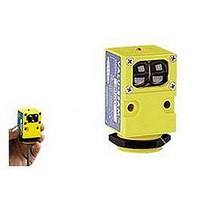
Photoelectric Sensor
Manufacturer
BANNER ENGINEERING
Datasheet
1.SM912LV.pdf
(20 pages)
Specifications of SM912LV
Output Current
250mA
Sensor Output
NPN/PNP
Supply Voltage Range Dc
10V To 30V
Sensing Range Max
9m
Sensor Housing
Rectangular
Switch Terminals
Cable
Sensor Input
Optical
Sensing Mode
Retroreflective


VALU-BEAM 912 Series Sensors
Hookup Diagrams for ac SM2A912 Series Sensors
Basic ac Hookup
For emitter hookup, see preceding page.
VALU-BEAM 2-wire ac sensors wire in series
with an appropriate load. This combination, in
turn, wires across the ac line.
These sensors operate in the range of 24 to
250V ac, and may be programmed for either
normally open (N.O.) or normally closed (N.C.)
operation by way of the light-dark operate
switch on the back of the sensor. A 2-wire ac
sensor may be connected exactly like a me-
chanical limit switch.
The sensor remains powered when the load is
"off" by a residual current which flows through
the load. The off-state leakage current (
always less than 1.7mA. The effect of this
leakage current depends on the characteristics
of the load. The voltage which appears across
the load in the off-state is equal to the leakage
current of the sensor multiplied by the resis-
tance of the load:
If this resultant off-state voltage is less than the
guaranteed turn-off voltage of the load, then the
interface is direct. If the off-state voltage
causes the load to stay "on", then an artificial
load resistor must be connected in parallel with
the load to lower the effective resistance. Most
loads, including most programmable controller
inputs, will interface to 2-wire sensors with
1.7mA leakage current without an artificial
load resistor. These sensors are not polarity
sensitive: all hookups are without regard to
wire color.
WARNING: VALU-BEAM 2-wire ac sensors
will be destroyed if the load becomes a short
circuit!!
Connection to
Programmable Controllers
Hookup shown is typical for
all inputs.
ac "hot"
L1
L1
V
Vac
off
= 1.7mA x R
24 to 250V ac
ac neutral
L2
I
off = <1.7mA
LOAD
Hookup shown
is typical for
all inputs
load
neutral
1
2
3
4
5
6
7
8
N
P
U
S
T
I
L2
I
g.
P
C
o
l.
r
r
t
off
) is
AC Sensors in Series
AC Sensors in Parallel
Multiple 2-wire ac VALU-BEAMs may be wired
in parallel to a load for "OR" or "NAND" logic
functions. With sensors wired in parallel, the off-
state leakage current through the load is equal to the
sum of the leakage currents required by the indi-
vidual sensors. Consequently, loads with high
resistance like small relays and solid state inputs
may require artificial load resistors.
AC VALU-BEAMs wired together in parallel will
not cause momentary drop-out of the load, as is
experienced when wiring in parallel with contacts
(see below). However, it is likely that the power-
up delay feature will cause a momentary drop-out
of the load if an ac VALU-BEAM is wired in
parallel with a different brand or model of 2-wire
sensor. Contact the Banner applications group to
verify compatibility.
AC Sensors in Series
with Contacts
When 2-wire ac sensors are connected in series
with mechanical limit switch or relay contacts, the
sensor will receive power to operate only when all
of the contacts are closed. The false-pulse protec-
tion circuit of the sensor will cause a 0.3 second
delay between the time the contacts close and the
time that the load can energize.
Multiple 2-wire ac VALU-BEAMs may be wired
together in series for "AND" or "NOR" logic func-
tions. The maximum number of sensors which may
be wired in series to a load depends upon the level
of the line voltage and the switching characteristics
of the load. Each sensor connected in series adds an
amount of voltage drop across the load. The
amount of voltage drop that each sensor adds
depends upon the current demand of the load. Each
sensor in series adds approximately 5 volts drop
across a 500mA load. A 15mA load will see about
a 10 volt drop from each sensor added in series. To
determine compatibility, compare the resultant on-
state voltage across the load against the load's
guaranteed turn-on voltage level (from the
manufacturer's specifications).
L1
0.3 second delay
when contact closes
24 to 250V ac
LOAD
L2
L1
Most non-compatibility of series-connected sen-
sors with loads occurs in low-voltage applications
(e.g. 12, 24, or 48V ac circuits) where the on-state
voltage drop across the load is a significant per-
centage of the supply voltage. The power-up in-
hibit time (up to 300 milliseconds per sensor) is
also additive.
AC Sensors in Parallel
with Contacts
L1
When 2-wire ac sensors are connected in parallel
with mechanical switch or relay contacts, the
sensor loses the current it needs to operate while
any contact is closed. When all of the contacts
open, the sensor's 0.3 second power-up delay
may cause a momentary drop-out of the load.
<1.7mA
<1.7mA
L1
NOTE: maximum load capacity
of output is 500mA.
0.3 second delay
when contact opens
24 to 250V ac
24 to 250V ac
24 to 250V ac
I
off = <3.4mA
LOAD
LOAD
LOAD
L2
L2
L2
9
Related parts for SM912LV
Image
Part Number
Description
Manufacturer
Datasheet
Request
R

Part Number:
Description:
Photoelectric Sensor
Manufacturer:
BANNER ENGINEERING
Datasheet:

Part Number:
Description:
Photoelectric Sensor
Manufacturer:
BANNER ENGINEERING
Datasheet:

Part Number:
Description:
LEDIR70XD4-XM-81039 MAX INTENS STROBE ONLY NO BANNER MARKS
Manufacturer:
BANNER ENGINEERING
Part Number:
Description:
M18SP6DL-72225 LABELED MOELLER NO BANNER MARKINGS BULK PACK
Manufacturer:
BANNER ENGINEERING
Part Number:
Description:
M18SP6DLQ-72226 LABLED MOELLER NO BANNER MARKINGS BULK PACK
Manufacturer:
BANNER ENGINEERING
Part Number:
Description:
M18SP6L-72223 LABELED MOELLER NO BANNER MARKINGS BULK PACK
Manufacturer:
BANNER ENGINEERING
Part Number:
Description:
M18SP6LQ-72224 LABELED MOELLER NO BANNER MARKINGS BULK PACK
Manufacturer:
BANNER ENGINEERING
Part Number:
Description:
P4D1-77908 P4 DRIVER GENERIC NO BANNER MARKINGS RESALE TO CUSTOMER
Manufacturer:
BANNER ENGINEERING
Part Number:
Description:
Photoelectric Sensor
Manufacturer:
BANNER ENGINEERING
Datasheet:

Part Number:
Description:
Programmable Indicator Light
Manufacturer:
BANNER ENGINEERING
Datasheet:
Part Number:
Description:
INDICATOR LED PANEL 50MM GRN/RED/YEL 30V
Manufacturer:
BANNER ENGINEERING
Datasheet:
Part Number:
Description:
Programmable Indicator Light
Manufacturer:
BANNER ENGINEERING
Datasheet: