SMU315LP BANNER ENGINEERING, SMU315LP Datasheet - Page 8
SMU315LP
Manufacturer Part Number
SMU315LP
Description
Photoelectric Sensor
Manufacturer
BANNER ENGINEERING
Type
Retroreflectiver
Specifications of SMU315LP
Output Current
3A
Sensor Output
Relay
Supply Voltage Range Dc
24V To 240V
Contact Current Max
3A
Switch Terminals
Cable
Sensing Range Min
10mm
Sensor Input
Optical
Output Type
Relay
Sensing Range Max
3m
Brand/series
Mini-Beam®
Current, Switching
3 A
Function
Proximity
Indicator
LED
Ip Rating
IP67
Light Source
Visible Red LED
Material, Body
ABS
Material, Cover
Clear Acrylic
Material, Lens
Acrylic
Mounting Type
Panel
Output
Relay
Primary Type
Photoelectric
Range, Measurement
3 m
Response Time
20 ms (Max.)
Sensing Mode
Polarized Retro-Reflective
Standards
UL Listed
Technology
Photoelectric
Temperature, Operating
-20 to +55 °C
Termination
Cable
Voltage, Supply
240 VAC/VDC
Voltage, Switching
250/30 VAC/VDC
Lead Free Status / Rohs Status
RoHS Exempt Product


MINI-BEAM Universal Voltage Series
Proper operation of these sensors requires that they be mounted securely and aligned
properly. Excessive sensor movement or vibration (or movement or vibration of the
fiber tips, in the case of fiber-optic sensors) can result in loss of alignment to the
target object, eventually leading to intermittent or false operation. Banner offers a
complete selection of mounting brackets (see page 9-10); contact the factory for
additional mounting suggestions.
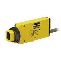
MINI-BEAM Universal Voltage sensors (except opposed-mode emitters) have two
adjustments: Gain and Light/Dark Operate, plus a Signal Strength indicator LED on
the back of the sensor, protected behind a clear acrylic cover (see Figure 1).
Gain
To increase Gain, turn the 15-turn potentiometer clockwise. It is clutched at both ends
of travel to avoid damage. A “clicking” sound may be heard and/or felt when
attempting to adjust beyond either limit.
Signal Strength Indicator LED
The Signal Strength indicator is Banner’s exclusive, patented AID (Alignment
Indicating Device). Its pulse rate increases as the received light signal strength
increases. This simplifies accurate alignment and gives a relative indication of sensing
contrast.
Light/Dark Operate Select
In Light Operate mode, the sensor output relay energizes when the lighter of the two
conditions is present; in Dark Operate mode, the relay energizes when the darker of
the two conditions is present.
To select Light Operate, insert a small screwdriver into the slot on the select switch
and turn it fully clockwise, until the tabs on the control touch the stop; to select Dark
Operate, turn the select switch fully counterclockwise, until the tabs touch the
opposite side of the stop.
NOTE: Take care when turning the Light/Dark Operate select switch, that the small
MINI-BEAM Universal Voltage Series sensors have no field-serviceable parts, other
than replaceable lenses (see page 9).
page
Installation and Alignment
Normal Operation
Troubleshooting
8
tabs on the switch do not become damaged.
Using the MINI-BEAM Universal Voltage Sensor
Banner Engineering Corp. • Minneapolis, U.S.A.
Website: http://www.baneng.com • Tel: 888.373.6767
Figure 1. MINI-BEAM Universal Voltage
Series indicators
Related parts for SMU315LP
Image
Part Number
Description
Manufacturer
Datasheet
Request
R

Part Number:
Description:
Photoelectric Sensor
Manufacturer:
BANNER ENGINEERING
Datasheet:

Part Number:
Description:
Photoelectric Sensor
Manufacturer:
BANNER ENGINEERING
Datasheet:

Part Number:
Description:
LEDIR70XD4-XM-81039 MAX INTENS STROBE ONLY NO BANNER MARKS
Manufacturer:
BANNER ENGINEERING
Part Number:
Description:
M18SP6DL-72225 LABELED MOELLER NO BANNER MARKINGS BULK PACK
Manufacturer:
BANNER ENGINEERING
Part Number:
Description:
M18SP6DLQ-72226 LABLED MOELLER NO BANNER MARKINGS BULK PACK
Manufacturer:
BANNER ENGINEERING
Part Number:
Description:
M18SP6L-72223 LABELED MOELLER NO BANNER MARKINGS BULK PACK
Manufacturer:
BANNER ENGINEERING
Part Number:
Description:
M18SP6LQ-72224 LABELED MOELLER NO BANNER MARKINGS BULK PACK
Manufacturer:
BANNER ENGINEERING
Part Number:
Description:
P4D1-77908 P4 DRIVER GENERIC NO BANNER MARKINGS RESALE TO CUSTOMER
Manufacturer:
BANNER ENGINEERING
Part Number:
Description:
Photoelectric Sensor
Manufacturer:
BANNER ENGINEERING
Datasheet:

Part Number:
Description:
Programmable Indicator Light
Manufacturer:
BANNER ENGINEERING
Datasheet:
Part Number:
Description:
INDICATOR LED PANEL 50MM GRN/RED/YEL 30V
Manufacturer:
BANNER ENGINEERING
Datasheet:
Part Number:
Description:
Programmable Indicator Light
Manufacturer:
BANNER ENGINEERING
Datasheet: