E3ZD66 Omron, E3ZD66 Datasheet - Page 12
E3ZD66
Manufacturer Part Number
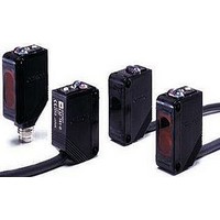
E3ZD66
Description
Photoelectric Sensor
Manufacturer
Omron
Datasheet
1.E3Z-D61.pdf
(18 pages)
Specifications of E3ZD66
Output Current
100mA
Sensor Output
NPN
Supply Voltage Range Dc
12V To 24V
Reflector Distance Min
0.2"
Mounting Type
Bracket
Switch Terminals
Cable
Reflector Distance Max
3.9"
Supply Voltage Min
12VDC
Lead Free Status / RoHS Status
Lead free / RoHS Compliant


I/O Circuit Diagrams
NPN Output
PNP Output
E3Z-T61(K)
E3Z-T66
E3Z-T62
E3Z-T67
E3Z-T61A
E3Z-T66A
E3Z-R61(K)
E3Z-R66
E3Z-D61(K)
E3Z-D66
E3Z-D62(K)
E3Z-D67
E3Z-L61
E3Z-L66
E3Z-T62-G0
E3Z-T67-G0
E3Z-T81(K)
E3Z-T86
E3Z-T82
E3Z-T87
E3Z-T81A
E3Z-T86A
E3Z-R81(K)
E3Z-R86
E3Z-D81(K)
E3Z-D86
E3Z-D82(K)
E3Z-D87
E3Z-L81
E3Z-L86
E3Z-T82-G0
E3Z-T87-G0
Model
Model
Through-beam Emitter
Through-beam Emitter
Operation
Operation
Light-ON
Dark-ON
Light-ON
Dark-ON
mode
mode
---
---
Emission
stop input
LED for
emission
Indicator
(orange)
(Between brown (1) and black (4) leads)
(Between brown (1) and black (4) leads)
Emission
stop input
LED for
emission
Indicator
(orange)
Operation
indicator
(orange)
Operation
indicator
(orange)
Load
(e.g., relay)
Output
transistor
Load
(e.g., relay)
Output
transistor
Load
(e.g., relay)
Operation
indicator
(orange)
Output
transistor
Load
(e.g., relay)
Operation
indicator
(orange)
Output
transistor
(Between brown (1) and pink (2) leads)
(Between blue (3) and black (4) leads)
(Between blue (3) and black (4) leads)
(Between blue (3) and pink (2) leads)
No incident light
No incident light
No incident light
No incident light
Incident light
Incident light
Incident light
Incident light
Timing charts
Timing charts
OFF
OFF
OFF
Operate
Operate
Operate
Operate
OFF
OFF
OFF
ON
ON
ON
ON
ON
ON
Reset
Reset
Reset
Reset
OFF
OFF
OFF
OFF
OFF
OFF
OFF
OFF
ON
ON
ON
ON
ON
ON
ON
ON
Power
indicator
(orange)
Power
indicator
(orange)
Photo-
electric
Sensor
main
circuit
Photo-
electric
Sensor
Main
Circuit
(LIGHT ON)
(LIGHT ON)
(DARK ON)
(DARK ON)
Operation
Operation
selector
selector
D side
D side
L side
L side
---
---
1
3
Brown
Blue
1
3
Brown
Blue
Through-beam Emitter
Through-beam Emitter
Through-beam Receivers, Retro-reflective Models,
Diffuse-reflective Models
Through-beam Receivers, Retro-reflective Models, Diffuse-reflective Models.
Operation
indicator
(Orange)
Connector Pin Arrangement
Operation
indicator
(Orange)
(Orange)
Power indicator
(Orange)
Power indicator
Pin 2 is not used.
(Green)
12 to
24 VDC
Stability
indicator
12 to 24 VDC
Connector Pin Arrangement
1
Photo-
electric
Sensor
main
circuit
Photo-
electric
Sensor
main
circuit
Connector Pin Arrangement
2
Photo-
electric
Sensor
main
circuit
(Green)
4
Pins 2 and 4 are not used.
Stability
indicator
Connector Pin
3
Arrangement
Pins 2 and 4
are not used.
Pin 2 is not used.
1
Photo-
electric
Sensor
main
circuit
2
Output circuit
Output circuit
1
4
1
2
1
2
3
2
1
2
3
3
Brown
Brown
Blue
Blue
Pink
Pink
4
(Control
4
output)
3
3
(Emission
(Emission
stop input)
e-CON Connector Pin Arrangement
stop input)
(Control
Z
12 to 24 VDC
12 to 24 VDC
output)
D
1
4
3
1
2
3
4
1
2
3
4
Brown
Black
Blue
0 V
0 V
Z
Press fit
Press fit
D
e-CON Connector
Pin Arrangement
100 mA
max.
1
4
3
Blue
Brown
Black
Connector Pin Arrangement
Connector Pin Arrangement
12 to 24 VDC
100 mA
max.
1
2
3
4
(Relay)
1
2
3
4
Load
Pin 4 is not used.
0 V
Pin 4 is not used.
Clamp type
Clamp
12 to 24 VDC
1
(Relay)
2
Load
1
0 V
2
4
3
4
3
E3Z
12
Related parts for E3ZD66
Image
Part Number
Description
Manufacturer
Datasheet
Request
R

Part Number:
Description:
G6S-2GLow Signal Relay
Manufacturer:
Omron Corporation
Datasheet:
Part Number:
Description:
Compact, Low-cost, SSR Switching 5 to 20 A
Manufacturer:
Omron Corporation
Datasheet:
Part Number:
Description:
Manufacturer:
Omron Corporation
Datasheet:
Part Number:
Description:
Manufacturer:
Omron Corporation
Datasheet:
Part Number:
Description:
Manufacturer:
Omron Corporation
Datasheet:
Part Number:
Description:
Manufacturer:
Omron Corporation
Datasheet:
Part Number:
Description:
Manufacturer:
Omron Corporation
Datasheet:
Part Number:
Description:
Manufacturer:
Omron Corporation
Datasheet: