SCX15AN SENSYM, SCX15AN Datasheet - Page 4
SCX15AN
Manufacturer Part Number
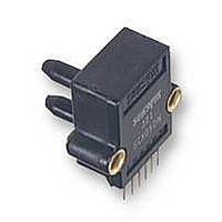
SCX15AN
Description
PRESSURE SENSOR, 0-15PSIA
Manufacturer
SENSYM
Datasheet
1.SCX01DN.pdf
(10 pages)
Specifications of SCX15AN
External Depth
26.2mm
External Length / Height
25.4mm
External Width
27.9mm
Fixing Centres
21.6mm
Hysteresis
0.5%
Lead Spacing
2.54mm
Linearity
0.5%
Operating Pressure Range
0 To 15psia
Available stocks
Company
Part Number
Manufacturer
Quantity
Price


SCX Series
Precision compensated pressure sensors
APPLICATION INFORMATION
The following circuits show some typical designs using the SCX
series sensors. For specific applications information or assistance,
please contact your nearest Sensym sales office or the Sensym
factory.
Low pressure applications
For sensing pressures below 1 psi, the circuit shown in Figure A
uses the SCX01DN to provide a 2 to 5 V output for a 0 to 10 inch of
water column input pressure. This output signal is compatible with
many A/D converters and hence can be used to interface to a
microprocessor system. This low-cost circuit is easily adaptable to
lower full-scale pressures down to 5 inches of water column.
Circuit description
The LM10 is used to provide a voltage reference for the excitation
voltage (V
V
V power supply. R
voltage at the output, V
The pressure signal, V
Sensym Application Note SSAN-17A for details on this amplifier)
R
is given below.
For the best circuit performance, a careful selection of components
in necessary. Use wirebound pots of insure low temperature
coefficients and low longterm drift. A five-element resistor array
(10kΩ) SIP should be used for the resistors in the amplifier stage in
order to obtain closely matched values and temperature coefficients.
All other resistors should be 1% metal film. Amplifiers B
should have low offset voltage and low noise. Signal lines should
be as short as possible and the power supply should be capacitively
bypassed on the PC board.
4/10
E
2
and V
is used to adjust the signal gain of the circuit. The output equation
REF
E
), and for the voltage node V
are not affected by noise or voltage variations in the 12
V
OUT
3
is used to adjust V
= V
IN
OUT
, is amplified by amplifiers B
IN
.
[ 2 (1+
Physical construction (cutaway diagram) (not drawn to scale)
R
/
R1
)]+V
REF
REF
. With this configuration,
REF
to set the initial offset
1
, and B
1
, and B
2
(see
2
Adjustment procedure
1. With zero-pressure applied, adjust the offset adjust R
2. Apply full-scale pressure (10 in. W.C) to port B
3. Repeat procedure if necessary.
Medical applications
For blood pressure monitoring applications, the circuit shown in
Figure B provides a 0.5 V to 3.5 V output for a 0 to 300 mm Hg input
pressure. The circuit is easily calibrated and is not affected by
changes in the voltage supply. Because 300 mm Hg is approximately
5.8 psi, an SCX05DN is used.
Circuit description
The circuit shown here in Figure B is very similar to that shown in
Figure A. The internal 200 mV reference voltage of the LM10 is
amplified to provide power to the sensor and to provide a voltage
reference, V
between 5 and 20 volts without affecting performance of the circuit.
By adjusting R
at V
B
voltages and high common-mode rejection. The signal gain is
adjusted by R
given by ,
Adjustment procedure
1. With zero-pressure applied, adjust the offset adjust
2. Apply full-scale pressure (300 mm Hg) to port B
3. Repeat procedure if necessary.
2
. These amplifiers should be precision op amps with low offset
until V
full-scale adjust R
R
R
OUT
3
2
, until V
, until V
. The pressure signal, V
OUT
REF
= 2.000 V
2
OUT
OUT
3
. This allows the circuit to operate at a supply voltage
, and the overall equation for the output voltage is
, V
V
OUT
= 0.500 V
= 3.500 V.
REF
= V
is used to set the initial zero-pressure voltage
2
, so that V
IN
www.sensortechnics.com
[ 2 (1+
IN
, is amplified by amplifiers B
OUT
R
/
= 5.000 V.
R1
)]+V
REF
August 2005 / 053
1
and adjust the
1
and adjust
3
,
1
and
Related parts for SCX15AN
Image
Part Number
Description
Manufacturer
Datasheet
Request
R

Part Number:
Description:
PRESSURE SENSOR, 0-1PSID
Manufacturer:
SENSYM
Datasheet:
Part Number:
Description:
PRESSURE SENSOR, 0-5PSID
Manufacturer:
SENSYM
Datasheet:
Part Number:
Description:
PRESSURE SENSOR, 0-100PSID
Manufacturer:
SENSYM
Datasheet:
Part Number:
Description:
PRESSURE SENSOR, 0-15PSID
Manufacturer:
SENSYM
Datasheet:
Part Number:
Description:
PRESSURE SENSOR, 0-30PSID
Manufacturer:
SENSYM
Datasheet:

Part Number:
Description:
PRESSURE SENSOR, 0-5" H2O
Manufacturer:
SENSYM
Datasheet:
Part Number:
Description:
PRESSURE SENSOR, 0-10" H2O
Manufacturer:
SENSYM
Datasheet:
Part Number:
Description:
PRESSURE SENSOR, 0-1PSID
Manufacturer:
SENSYM
Datasheet:

Part Number:
Description:
PRESSURE SENSOR, 0-1PSIG
Manufacturer:
SENSYM
Datasheet:
Part Number:
Description:
PRESSURE SENSOR, 0-100PSIG
Manufacturer:
SENSYM
Datasheet:

Part Number:
Description:
PRESSURE SENSOR, 0-15PSIA
Manufacturer:
SENSYM
Datasheet:
Part Number:
Description:
PRESSURE SENSOR, 0-15PSID
Manufacturer:
SENSYM
Datasheet:
Part Number:
Description:
PRESSURE SENSOR, 0-15PSIG
Manufacturer:
SENSYM
Datasheet:

Part Number:
Description:
PRESSURE SENSOR, 0-100PSI
Manufacturer:
SENSYM
Datasheet:

Part Number:
Description:
Transducer
Manufacturer:
Honeywell / SenSym
Datasheet: