E2E2-X10C1M1 Omron, E2E2-X10C1M1 Datasheet - Page 8
E2E2-X10C1M1
Manufacturer Part Number
E2E2-X10C1M1
Description
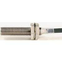
Inductive Proximity Sensor
Manufacturer
Omron
Datasheet
1.E2E2-X5B1-M1.pdf
(9 pages)
Specifications of E2E2-X10C1M1
Sensor Input
Inductive
Sensing Range
10mm
Supply Voltage Range Dc
10V To 55V
Sensor Housing
Barrel
Supply Voltage Max
40VDC
Sensing Range Max
10mm
Mounting Type
Panel
Output Type
NPN, NO
Switch Terminals
Connector
Load Current Rms Max
200mA
Sensing Face Diameter
30mm
Rohs Compliant
Yes
Lead Free Status / RoHS Status
Lead free / RoHS Compliant


J EFFECTS OF SURROUNDING METAL
When mounting the E2E2 within a metal panel, ensure that the
clearances given in the table below are maintained. Failure to
maintain these distances may cause deterioration in the perfor-
mance of the sensor.
J MUTUAL INTERFERENCE
When installing two or more Sensors face to face or side by side,
ensure that the minimum distances given in the following table
are maintained.
J INSTALLATION
Power Reset Time
The Proximity Sensor is ready to operate within 100 ms after
power is supplied. If power supplies are connected to the
Proximity Sensor and load respectively, be sure to supply power
to the Proximity Sensor before supplying power to the load.
Power OFF
The Proximity Sensor may output a pulse signal when it is turned
off. Turn off the load before turning off the Proximity Sensor.
Power Supply Transformer
When using a DC power supply, make sure that the DC
power supply has an insulated transformer. Do not use a DC
power supply with an auto-transformer.
Target Object
Metal Coating
The sensing distances of the Proximity Sensor vary with the
metal coating on target objects.
J WIRING
High-tension Lines
Wiring through Metal Conduit
If there is a power or high-tension line near the cable of the
Proximity Sensor, wire the cable through an independent metal
conduit to prevent against Proximity Sensor damage or
malfunctioning.
E2E2 3-Wire DC
Type
Shielded
Unshielded
Type
Shielded
Unshielded
Dimension
ℓ
d
D
m
n
ℓ
d
D
m
n
Dimension
A
B
A
B
M12
0 mm
12 mm
0 mm
8 mm
18 mm
15 mm
40 mm
15 mm
20 mm
36 mm
M12
30 mm
20 mm
120 mm
100 mm
9
Cable Tractive Force
Do not pull cables with the tractive forces exceeding these specs.
J MOUNTING
The Proximity Sensor must not be subjected to excessive shock
with a hammer when it is installed, or the Proximity Sensor may
be damaged or lose its water-resistance.
J ENVIRONMENT
Water Resistance
Do not use the Proximity Sensor underwater, outdoors, or in the
rain.
Operating Environment
Be sure to use the Proximity Sensor within its operating ambient
temperature range and do not use the Proximity Sensor outdoors
so that its reliability and life expectancy can be maintained.
Although the Proximity Sensor is water resistant, a cover to pro-
tect the Proximity Sensor from water or water-soluble machining
oil is recommended so that its reliability and life expectancy can
be maintained.
Do not use the Proximity Sensor in an environment with chemical
gas (e.g., strong alkaline or acid gasses including nitric, chromic,
and concentrated sulfuric acid gases).
Diameter
4 mm dia. max.
4 mm dia. min.
M18
0 mm
18 mm
0 mm
20 mm
27 mm
22 mm
55 mm
22 mm
40 mm
54 mm
M18
50 mm
35 mm
200 mm
110 mm
A
Tractive force
30 N max.
50 N max.
B
d dia.
M30
0 mm
30 mm
0 mm
40 mm
45 mm
30 mm
90 mm
30 mm
70 mm
90 mm
M30
100 mm
70 mm
300 mm
200 mm
E2E2 3-Wire DC
Related parts for E2E2-X10C1M1
Image
Part Number
Description
Manufacturer
Datasheet
Request
R

Part Number:
Description:
E2E2-X5MB1 W/ M12 CONNECTOR
Manufacturer:
Omron
Datasheet:

Part Number:
Description:
PROX LONG M30, 10mm NPN-NC 2M
Manufacturer:
Omron
Datasheet:
Part Number:
Description:
PROX LONG M18, 10mm PNP-NO 2M
Manufacturer:
Omron
Datasheet:
Part Number:
Description:
PROX LONG M18,10mm NPN-NO 2M
Manufacturer:
Omron
Datasheet:

Part Number:
Description:
PROX LONG M30,10mm AC2W-NO(COO
Manufacturer:
Omron
Datasheet:
Part Number:
Description:
PROX LONG M12,2mm NPN-NC 2M
Manufacturer:
Omron
Datasheet:
Part Number:
Description:
PROX LONG M12,2mm AC2W-NC 2M
Manufacturer:
Omron
Datasheet:
Part Number:
Description:
PROX LONG M18,5mm NPN-NC 2M
Manufacturer:
Omron
Datasheet: