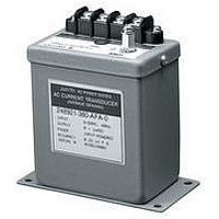
2469-53-54-0-AFA-1 YOKOGAWA, 2469-53-54-0-AFA-1 Datasheet - Page 9

2469-53-54-0-AFA-1
Manufacturer Part Number
2469-53-54-0-AFA-1
Description
TRANSDUCER, WATT, 60HZ, 0-1mA DC
Manufacturer
YOKOGAWA
Datasheet
1.2469-32-33-2-AHD-1.pdf
(15 pages)
Specifications of 2469-53-54-0-AFA-1
Transducer Function
Watt 3P3W (2 Element)
Transducer Input Current Ac
1A
Transducer Output Type
0-1mADC
Frequency
60Hz
Supply Voltage
120VAC
Lead Free Status / RoHS Status
na
1) GENERAL
2) SPECIFICATIONS
3) STANDARD MODELS
NOTE: See order format on next page for additional ratings, frequency calibrations, power-up and output options.
Model #
Current input / range
Current input over range capability
Current input burden
Voltage inputs and range:
Voltage input burden per element
Sustained Voltage input overange
Rated outputs
Accuracy: 0 ± 1mA output Watts
External calibration adjustment
Response time
Output ripple
Isolation
(Watt & VAR outputs are not isolated
from each other)
Surge Withstand Capability
Insulation resistance
Operating temperature
Operating humidity
Temperature effect
External magnetic field
Influence : unbalanced currents /
phase interaction / Power Factor
Influence of frequency
Weight
Shock
Vibration
UL Recognition
120 VAC, 5AAC, 60 Hz, input powered
W/V 1P2W, 0±1mA output (1 Element)
W/V 1P2W, 4-20mA output (1 Element)*
W/V 3P3W, 0±1mA output (2 Element)
W/V 3P3W, 4-20mA output (2 Element)*
W/V 3P4W, 0±1mA output (2
W/V 3P4W, 4-20mA output (2
W/V 3P4W, 0±1mA output (3 Element)
W/V 3P4W, 4-20mA output (3 Element)*
The 2469 and 2489 combined WATT/VAR transducers produce an analog output equal to the WATTS and
VARS measured by the input.
*VAR outputs for “AHD” are 12±8 mADC (see output options on next page).
Auxiliary power supply options <5.0 burden.
Input powered range
Auxiliary powered range
0 ± 1mA output VARS
4-20mA output
J U X T A
C O M B I N A T I O N
1
⁄
1
2
⁄
2
Element)
Element)*
0 to ±1mADC into a 10kΩ max. load; 10VDC output compliance
0.3% of span peak-to-peak max. 0.5% of span peak-to-peak max.
150% of rated input without damage (Auxiliary powered only)
<0.25%, 45-65 Hz, fundamental through 9th harmonic (Watt only)
100-135VAC
IEEE472/ANSI C37.90.1 - 1989, JIS C1111 (5KV 1.2 x 50 microseconds)
4-20 mADC into 750Ω max. load; 15VDC output compliance
10 to 200% of rated input
< 0.5VA
120V
Span: ± 2% minimum
2469 (0.5% Accuracy)
Zero: ± 1% minimum
246941-540-AFB-0-M
246941-540-AHD-0-M
246943-540-AFB-0-M
246943-540-AHD-0-M
246944-540-AFB-0-M
246944-540-AHD-0-M
246945-540-AFB-0-M
246945-540-AHD-0-M
0-120% rated input
±0.5% of full scale
±250 PPM / °C of span
W A T T / V A R
> 10 megohm / 500VDC input/output/power/case
±0.5% of full scale
12
±0.5% of span
<0.2% after 16.7 Hz, 4 mmp-p 1 hour, 3 Axis
0 - 90% relative humidity (non-condensing)
2500 VAC input to output, power and case
2000 VAC aux. power to output and case
<0.2% after 50G, 3 Axis and 6 repetitions
<0.5%
2469
< 400 milliseconds (0-99% of output)
1000% of rated input for 5 seconds
200% of rated input continuous
200-264VAC
0-1 Amp AC or 0-5 Amp AC
< 1.0VA
500 VAC output to case
< 0.2VA per element
240V
< 0.2% at 400 AT/m
1200g (2.65 lbs.)
-20°C to +60°C
T R A N S D U C E R S
File # E60579
± 0.1% of reading. ± 0.1% full scale
± 0.1% of reading. ± 0.05% full scale
1mA = W ± 50FS, V ±75span (PPM/°C)
85-135VAC
< 0.3VA
Span: ± 10% minimum
0-200% of rated input
0-120% of rated input
120V
2489 (0.2% Accuracy)
Zero: ± 5% minimum
248941-540-AFB-0-M
248941-540-AHD-0-M
248943-540-AFB-0-M
248943-540-AHD-0-M
248944-540-AFB-0-M
248944-540-AHD-0-M
248945-540-AFB-0-M
248945-540-AHD-0-M
± 0.2% of span
<0.2%
2489
170-264VAC
< 0.6VA
240V


