XX512A1KAM8 SQUARE D, XX512A1KAM8 Datasheet - Page 2
XX512A1KAM8
Manufacturer Part Number
XX512A1KAM8
Description
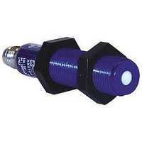
Ultrasonic Sensor
Manufacturer
SQUARE D
Datasheet
1.XX512A1KAM8.pdf
(4 pages)
Specifications of XX512A1KAM8
Sensing Range Min
6mm
Switching Frequency
125Hz
Beam Angle
7°
External Diameter
12mm
Operating Temperature Range
-20°C To +65°C
Body Material
Plastic
Mounting Type
Threaded
Contact Rating
100mA
Leaded Process Compatible
No
Rohs Compliant
No
Lead Free Status / RoHS Status
Contains lead / RoHS non-compliant


Ultrasonic Sensors
12, 18, and 30 mm Plastic Tubular
DC
370
Dimensions
Sensing face
Sensing face
0.47 in.
12 mm
M30 x 1.5 mm-6g
3.73 in.
95 mm
0.71 in.
18 mm
18 mm x 1 mm
12 mm x 1 mm
0.79 in.
20 mm
1.5 in.
38 mm
2.91 in.
74 mm
2.01 in.
51 mm
18 mm
30 mm
12 mm
1.95 in.
50 mm
3.33 in.
85 mm
2.29 in.
58 mm
2.55 in.
65 mm
12 mm x 1 mm
M30X1.5
8 mm x 1 mm
M12X1
M18X1
thread
thread
thread
1.11 in.
28 mm
12, 18, and 30 mm Plastic Tubular/ DC
Features:
•
•
Operation
Output
Mode
12 mm Diameter – Nominal Sensing Range 2" (51 mm)
N.O.
18 mm Diameter – Nominal Sensing Range 5.98" (152 mm)
N.O.
30 mm Diameter – Nominal Sensing Range 3.2" (1 m)
N.O.
During set up and operation of the XX ultrasonic sensor continually and accurately measures the elapsed
time of every pulse echo reception after each pulse transmission. The transmitted pulse starts a clock to
register the elapsed time for the received echoes. Given the elapsed time, the sensor software calculates
the distance traveled to the object of surface and back to the sensor, using a D=TVs/2, D= Distance from
the sensor to the object; T = Elapsed time between the pulse transmission and its echo reception, Vs =
the Velocity of sound, approximately 1100 feet per second.
While the sensor is in operation, the calculated distance (D) between the sensor and the object is
compared to the distances associated with the fixed window limits. These limits are shown in the
illustration above as Dwi and Dwo. If D is within these limits, an output is generated. The output remains
on until the echo does not return or it returns from outside the window limits.
Normally open operation diagrams shown below for all the XX Ultrasonic ranges.
12 mm
30 mm
Connector
Amber LED is ON
when an object is
sensed
Yellow
LED
PNP or NPN output
Housing: Plastic
Orange LED is ON
when an object is
not sensed.
Erratic operation
within this range
Deadband
Pushbutton
Setup
Multicolor
LED
0.0 mm
(0.0")
0.0 mm
(0.0")
SHADED AREA
REPRESENTS THE
FIXED SENSING
WINDOW
Erratic operation
within this range
©1997-
Deadband
ECHO
Circuit
Type
PNP/NPN
PNP/NPN
PNP/NPN
50.8 mm
(2.00")
6.4 mm
(0.25")
D
V+
Red
black-wire PNP is active
Red LED is On when
2002 Schneider Electric All Rights Reserved
W H T
Near Limit
P NP
BL K
P NP
PULSE
Dwi
Near Limit
6.3 mm (0.25")
Sensing Field
Sensing Range
Small objects are
best sensed about
38.1 mm (1.5")
Multicolor LED
V+
Window
OBJECT
V+
(source)
(sin k)
W H T
BL K
Green
W H T
BL K
P NP
P NP
OFF
ON
Voltage
Range
12-24 Vdc
12-24 Vdc
12-24 Vdc
Far Limit
Dwo
V+
Black-wire PNP is N.O.
White-wire PNP is N.C.
Red
Far Limit
50.8 mm (2.00")
W H T
P NP
BL K
P NP
OFF
ON
990.6 mm
(39.00")
V+
(source)
V+
(sin k)
BL K
W H T
Off
Orange
LED
Amber
LED
W H T
P NP
BL K
P NP
Connection
Type
4 pin Nano
4 pin Micro
4 pin Micro
•
•
18 mm
Self-teach on 30 mm version
Mounting nuts included
Amber LED is ON
when an object is
within window
Green LED is ON
when power is
applied
Load Current
Maximum
100 mA
100 mA
100 mA
within this range
Erratic operation
0.0 mm
(0.0")
Deadband
19.1 mm
(0.75")
(source)
W H T
OFF
V+
(sink)
BL K
Ultrasonic
Frequency
500 kHz
500 kHz
200 kHz
Near Limit
25.4 mm
(1.00")
Fixed Sensing
V+
(source)
W H T
BL K
(sink)
Window
ON
Catalog
Number
XX512A1KAM8
XX518A1KAM12
XX630A1KAM12
Far Limit
152.4 mm
(6.00")
OFF
V+
(source)
(sink)
W H T
BL K
Amber
LED
10/02
Related parts for XX512A1KAM8
Image
Part Number
Description
Manufacturer
Datasheet
Request
R


Part Number:
Description:
Pushbutton, Non-Illum'd Red "STOP", Momentary, 1NO-1NC, Square 30mm, 10A, 600V
Manufacturer:
SQUARE D
Datasheet:

Part Number:
Description:
KITS,TWIDO? PROGRAMMABLE CONTROLLERS,KITS,TWIDOPACK STARTER KIT - ADVANCED LEVEL,PROGRAMMABLE CONTROLLERS,TWIDO? PROGRAMMABLE CONTROLLERS ,SQUARE D
Manufacturer:
SQUARE D

Part Number:
Description:
LAMPS,INDICATOR,STACKABLE,LAMPS, STACKABLE INDICATOR,VISUAL INDICATING SIGNALS,XVB SERIES INDICATING BANKS ,SQUARE D
Manufacturer:
SQUARE D
Part Number:
Description:
LAMPS,INDICATOR,STACKABLE,LAMPS, STACKABLE INDICATOR,VISUAL INDICATING SIGNALS,XVB SERIES INDICATING BANKS ,SQUARE D
Manufacturer:
SQUARE D
Datasheet:
Part Number:
Description:
I/O EXTENDER MODULE 4 D IN & 2 D OUTPUT
Manufacturer:
SQUARE D
Datasheet:
Part Number:
Description:
CB ACCESSORY, UNDERVOLTAGE TRIP 48V DC
Manufacturer:
SQUARE D
Datasheet: