XX512A1KAM8 SQUARE D, XX512A1KAM8 Datasheet - Page 3
XX512A1KAM8
Manufacturer Part Number
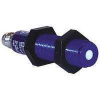
XX512A1KAM8
Description
Ultrasonic Sensor
Manufacturer
SQUARE D
Datasheet
1.XX512A1KAM8.pdf
(4 pages)
Specifications of XX512A1KAM8
Sensing Range Min
6mm
Switching Frequency
125Hz
Beam Angle
7°
External Diameter
12mm
Operating Temperature Range
-20°C To +65°C
Body Material
Plastic
Mounting Type
Threaded
Contact Rating
100mA
Leaded Process Compatible
No
Rohs Compliant
No
Lead Free Status / RoHS Status
Contains lead / RoHS non-compliant


10/02
Wiring
For additional cable options and lengths see p. 518
Connector Cables
(M8 or S suffix; M12 or D suffix)
XSZCS141
XSZCS151
XSZCD101Y
XSZCD111Y
1
Connector M8
Connector M12
BU/3
BN/1
PNP/NPN
2
4
1
4
3
2
3
Nano Conn., 4 pin, 2 m, straight
Nano Conn., 4 pin, 2 m, 90°
Micro Conn., 4 pin, 2 m, straight
Micro Conn., 4pin, 2 m, 90°
3 (-)
1 (+)
4 NPN Output
2 PNP Output
3 (-)
1 (+)
4 NPN Output
2 PNP Output
18 / 30 mm
BK/4
WH/2
12 mm
+
–
Specifications
Beam Plots
inches
Mechanical
Diameter
Nominal Sensing Range
Sensing Zone
Ultrasonic Cone Angle (see beam plots)
Temperature Range
Humidity
Enclosure Rating
Vibration
Shock
Repeat Accuracy
Maximum Angular Deviation
Minimum Size Detection
Enclosure Material
LED Indicators
Electrical
Rated Supply Voltage
Voltage Limits (including ripple)
Maximum Load Current
Voltage Drop; on-state
Residual Current; open state
Current Consumption, no load
Power Up Delay
On / Off Delay
Ultrasonic Frequency
Protection
Approvals
The beam plots below, were developed from data collected at 20 °C and zero air flow, which defines the
boundaries and shape of the sonic beams shown for the XX ultrasonic sensor range. The boundaries
were established using a 10 cm x 10 cm target positioned parallel to the sensor face, moved in and out
of the sensors operating range.
12 mm
30 mm
inches
cm
mm
0.0 0.2 0.4 0.6 0.8 1.0 1.2 1.4 1.6 1.8 2.0
0
0
0
Deadband
10
4
deadband
10
20
8
©
1997-2002 Schneider Electric All Rights Reserved
30
12
20
ESD
Overvoltage
Reverse Polarity
40
16
50
20
30
60
24
70
28
40
80
32
12 mm
2" (51 mm)
0.25 - 2.0" (6.4 - 50.8 mm)
7 °
- 4 to + 149 °F (- 20 to + 65 °C) + 32 to + 122 °F (0 to + 50 °C)
100 %
IP67
7 G @ 1 mm (F = 10 to 55 Hz)
30 G, 11 ms
+ / - 10 °
0.1" (2.5 mm) dia. rod
0.04" (1 mm) flat bar
Case: plastic; Sensing Face: silicon rubber / except 0.47" (12 mm) glass epoxy
LED ring
12 to 24 Vdc
10 to 28 Vdc
100 mA
0.79 V PNP / 0.58 V NPN
0.07 uA max.
20 mA
20 ms
500 kHz
Yes
Yes
Yes
CE
+ / - 0.027" (0.7 mm)
2 ms on / 2 ms off
90 100
50
36
40
60
110
mm inches
-10
-20
mm
20
10
0
400
300
200
100
0
-100
-200
-300
-400
-0.0
-0.1
-0.2
-0.3
-0.4
-0.5
0.5
0.4
0.3
0.2
0.1
-10
10
-2
-4
-6
-8
8
6
4
2
0
cm
18 mm
in.
12, 18, and 30 mm Plastic Tubular
sonic pattern measured by moving a large flat surface into the beam
0
0
1
18 mm
5.98" (152 mm)
1.0 - 6.0" (25.4 - 152.4 mm)
10 °
0.06" (1.59 mm) dia. rod
No LED
0.75 V PNP / 0.67 V NPN
0.05 uA max.
60 mA
350 ms
3 ms on / 3 ms off
deadband
5
2
3
10
4
5
15
Ultrasonic Sensors
6
7
20
8
30 mm
3.21’ (1 m)
2.0 - 39.0" (51 - 991 mm)
+ / - 0.034" (0.87 mm)
Two LED’s
0.75 V PNP / 0.33 V NPN
80 mA
720 ms
25 ms on / 25 ms off
9
25
10 11 12 13
DC, AC/DC
30
35
mm
120
80
40
0
-40
-80
-120
371
4
3
2
1
0
-1
-2
-3
-4
Related parts for XX512A1KAM8
Image
Part Number
Description
Manufacturer
Datasheet
Request
R


Part Number:
Description:
Pushbutton, Non-Illum'd Red "STOP", Momentary, 1NO-1NC, Square 30mm, 10A, 600V
Manufacturer:
SQUARE D
Datasheet:

Part Number:
Description:
KITS,TWIDO? PROGRAMMABLE CONTROLLERS,KITS,TWIDOPACK STARTER KIT - ADVANCED LEVEL,PROGRAMMABLE CONTROLLERS,TWIDO? PROGRAMMABLE CONTROLLERS ,SQUARE D
Manufacturer:
SQUARE D

Part Number:
Description:
LAMPS,INDICATOR,STACKABLE,LAMPS, STACKABLE INDICATOR,VISUAL INDICATING SIGNALS,XVB SERIES INDICATING BANKS ,SQUARE D
Manufacturer:
SQUARE D
Part Number:
Description:
LAMPS,INDICATOR,STACKABLE,LAMPS, STACKABLE INDICATOR,VISUAL INDICATING SIGNALS,XVB SERIES INDICATING BANKS ,SQUARE D
Manufacturer:
SQUARE D
Datasheet:
Part Number:
Description:
I/O EXTENDER MODULE 4 D IN & 2 D OUTPUT
Manufacturer:
SQUARE D
Datasheet:
Part Number:
Description:
CB ACCESSORY, UNDERVOLTAGE TRIP 48V DC
Manufacturer:
SQUARE D
Datasheet: