AZ7144 PANASONIC EW, AZ7144 Datasheet - Page 11
AZ7144
Manufacturer Part Number
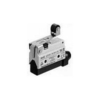
AZ7144
Description
LIMIT SWITCH, ROLLER LEVER, SPDT
Manufacturer
PANASONIC EW
Datasheet
1.AZ7121.pdf
(20 pages)
Specifications of AZ7144
Actuator Style
Roller Lever
Operating Force Max
2.75N
Contact Voltage Ac Max
250V
Contact Voltage Dc Max
115V
Contact Current Ac Max
10A
Contact Current Dc Max
400mA
Switch Terminals
Screw
Lead Free Status / RoHS Status
Lead free / RoHS Compliant


TECHNICAL INFORMATION
•
•
•
•
•
6
Current
EN60947-5-1
EN standard same as IEC947-5-1
Utilization categories
The following examples express the
classification of switches by category
of use.
Rated operational voltage (Ue)
The maximum rated voltage for
switch operation. This must never
exceed the maximum ratings insula-
tion voltage (Ui).
Rated operational current (Ie)
The maximum rated current for
switch operation.
Rated insulation voltage (Ui)
The maximum rated current value
which guards the switch’s insulation
functions, forming the parameters for
the resistance values and the mount-
ing distance.
type
AC
DC
Glossary relating to the EN60947-5-1
Category
AC-15
DC-12
Controls electromagnetic
loads in excess of 72VA
(Volt Amperes.)
Controls resistance
loads and semiconductor
loads.
Contents
•
•
•
•
•
Rated impulse withstand voltage
(Uimp)
The peak impulse current value
which enables the switch to resist
without insulation breakdown.
Rated enclosed thermal current
(Ithe)
The current value that enables cur-
rent to flow without exceeding the
specified maximum temperature in
the recharging contact switch. If the
pins are made of brass, the maxi-
mum temperature limit is 65°C 149°F.
Conditional short circuit current
The current the switch can resist
until the short circuit protection
device is activated.
Short circuit protection device
A device that protects the switch
from short circuits through a circuit
break (breakers, fuses, etc.)
Switching overvoltage
The surge momentarily generated
when a circuit is closed. Must be
lower than the Uimp value.
•
Pollution
Pollution degree
Expresses in levels the environment
in which the switch is used. The four
levels are shown below.
Limit switches come under contami-
nation level 3.
degree
1
2
3
4
No contamination or, even if conta-
mination is present, only non-con-
ducting contamination is generated.
Normally, only non-conducting cont-
amination is generated, but there
remains the possibility of temporary
conducting contamination when the
circuit is formed.
Conducting contamination is gener-
ated, or else dry non-conducting
contamination is generated by cir-
cuits which can be anticipated.
Permanent conducting contamina-
tion is generated by dust, rain,
snow, and other conductors.
Contents
Related parts for AZ7144
Image
Part Number
Description
Manufacturer
Datasheet
Request
R

Part Number:
Description:
POWER RELAY, 24VDC, 30A, SPST-NO
Manufacturer:
PANASONIC EW
Datasheet:

Part Number:
Description:
POWER RELAY, SPDT, 12VDC, 10A, PC BOARD
Manufacturer:
PANASONIC EW

Part Number:
Description:
POWER RELAY, 24VDC, 5A, SPST-NO, PCB
Manufacturer:
PANASONIC EW
Datasheet:


Part Number:
Description:
SIGNAL RELAY, DPDT, 4.5VDC, 1A, SMD
Manufacturer:
PANASONIC EW
Datasheet:

Part Number:
Description:
SIGNAL RELAY, DPDT, 4.5VDC, 1A, THD
Manufacturer:
PANASONIC EW
Datasheet:

Part Number:
Description:
MINIATURE RELAY, DPDT, 24VDC, 2A, THD
Manufacturer:
PANASONIC EW


Part Number:
Description:
SIGNAL RELAY, DPDT, 5VDC, 2A, PC BOARD
Manufacturer:
PANASONIC EW
Datasheet:
Part Number:
Description:
SIGNAL RELAY, DPDT, 5VDC, 2A, SURFACE MOUNT
Manufacturer:
PANASONIC EW
Datasheet:
Part Number:
Description:
SIGNAL RELAY, DPDT, 5VDC, 2A, PC BOARD
Manufacturer:
PANASONIC EW
Datasheet:


Part Number:
Description:
PHOTOMOS RELAY, 60VDC, 400mA
Manufacturer:
PANASONIC EW
Datasheet:

Part Number:
Description:
PHOTOMOS RELAY, 400V, 150mA
Manufacturer:
PANASONIC EW
Datasheet: