ATV12HU22M3 SQUARE D, ATV12HU22M3 Datasheet - Page 14
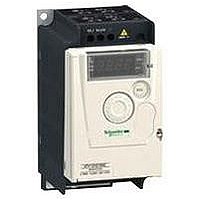
ATV12HU22M3
Manufacturer Part Number
ATV12HU22M3
Description
AC Drive
Manufacturer
SQUARE D
Specifications of ATV12HU22M3
No. Of Phases
Three
Power Rating
2.2kW
Output Voltage Max
230V
Output Current
10A
Supply Voltage Max
230V
Frequency Range
0.5 To 400Hz
Rohs Compliant
Yes
Lead Free Status / RoHS Status
Lead free / RoHS Compliant


10
1
2
3
4
5
6
7
8
9
Specifications
Available internal supplies
Analog input
Analog output
Relay outputs
LI logic inputs
Logic output
Maximum I/O wire size and tightening torque
Acceleration and deceleration ramps
Emergency braking
Main drive protection features
Motor protection
Frequency resolution
Time constant on a change of setpoint
Introduction:
page 8
Electrical specifications (control)
12
AI1
AO1
R1A, R1B, R1C
LI1 to LI4
Positive logic (Source)
Negative logic (Sink)
LO+, LO-
(continued)
References:
page 14
Altivar
variable speed drives
Dimensions:
page 18
ms
Protected against short-circuits and overloads:
One 5 V ⎓ supply (± 5%) for the reference potentiometer (2.2 to 10 kW),
maximum data rate 10 mA
One 24 V ⎓ supply (-15%/+20%) for the control inputs, maximum data rate 100 mA
1 software-configurable voltage or current analog input:
Voltage analog input: 0 to 5 V ⎓ (internal power supply only) or 0 to 10 V ⎓,
impedance 30 kW
Analog current input: X-Y mA by programming X and Y from 0 to 20 mA,
impedance 250 W
Sampling time: < 10 ms
Resolution: 10 bits
Accuracy: ± 1% at 25°C
Linearity: ± 0.3% of the maximum scale value
Factory setting: Input configured as voltage type
1 software-configurable voltage or current analog output:
Analog voltage output: 0 to 10 V ⎓ , minimum load impedance 470 W
Analog current output: 0 to 20 mA, maximum load impedance 800 W
Update time: < 10 ms
Resolution: 8 bits
Accuracy: ± 1% at 25°C
1 protected relay output, 1 N/O contact and 1 N/C contact with common point
Response time: 30 ms maximum
Minimum switching capacity: 5 mA for 24 V ⎓
Maximum switching capacity:
On resistive load (cos j = 1 and L/R = 0 ms): 3 A at 250 V a or 4 A at 30 V ⎓
On inductive load (cos j = 0.4 and L/R = 7 ms): 2 A at 250 V a or 30 V ⎓
4 programmable logic inputs, compatible with PLC level 1, standard IEC/EN 61131-2
24 V ⎓ internal power supply or 24 V ⎓ external power supply (min. 18 V, max. 30 V)
Sampling time: < 20 ms
Sampling time tolerance: ± 1 ms
Factory-set with 2-wire control in "transition" mode for machine safety reasons:
LI1: forward
LI2 to LI4: not assigned
Multiple assignment makes it possible to configure several functions on one input
(for example: LI1 assigned to forward and preset speed 2, LI3 assigned to reverse
and preset speed 3)
Impedance 3.5 kW
Factory setting
State 0 if < 5 V, state 1 if > 11 V
Software-configurable
State 0 if > 16 V or logic input not wired, state 1 if < 10 V
One 24 V ⎓ logic output assignable as positive logic (Source) or negative logic (Sink)
open collector type, compatible with level 1 PLC, standard IEC/EN 61131-2
Maximum voltage: 30 V
Linearity: ± 1%
Maximum current: 10 mA (100 mA with external power supply)
Impedance: 1 kW
Update time: < 20 ms
1.5 mm
0.5 Nm
Ramp profile:
Linear from 0 to 999.9 s
S ramp
U ramp
Automatic adaptation of deceleration ramp time if braking capacities exceeded,
although this adaptation can be disabled (use of braking unit)
By DC injection: automatically as soon as the estimated output frequency drops to
< 0.2 Hz, period adjustable from 0.1 to 30 s or continuous, current adjustable from
0 to 1.2 In
Thermal protection against overheating
Protection against short-circuits between motor phases
Overcurrent protection between motor phases and ground
Protection in the event of line overvoltage and undervoltage
Input phase loss protection, in three-phase
Thermal protection integrated in the drive by continuous calculation of the l
Display unit: 0.1 Hz
Analog inputs: 10-bit A/D converter
20 ± 1 ms
2
®
(14 AWG)
12
Connections:
page 22
Functions:
page 26
2
t
Related parts for ATV12HU22M3
Image
Part Number
Description
Manufacturer
Datasheet
Request
R


Part Number:
Description:
Pushbutton, Non-Illum'd Red "STOP", Momentary, 1NO-1NC, Square 30mm, 10A, 600V
Manufacturer:
SQUARE D
Datasheet:
Part Number:
Description:
CB ACCESSORY, UNDERVOLTAGE TRIP 48V DC
Manufacturer:
SQUARE D
Datasheet:
Part Number:
Description:
CB ACCESSORY, TRIP UNIT
Manufacturer:
SQUARE D
Datasheet: