ATV12HU22M3 SQUARE D, ATV12HU22M3 Datasheet - Page 31
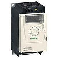
ATV12HU22M3
Manufacturer Part Number
ATV12HU22M3
Description
AC Drive
Manufacturer
SQUARE D
Specifications of ATV12HU22M3
No. Of Phases
Three
Power Rating
2.2kW
Output Voltage Max
230V
Output Current
10A
Supply Voltage Max
230V
Frequency Range
0.5 To 400Hz
Rohs Compliant
Yes
Lead Free Status / RoHS Status
Lead free / RoHS Compliant


Functions
PID
reference
PID
feedback
Introduction:
page 8
FBS: PID feedback multiplication coefficient
HSP: High speed
PIC: Change of direction of PID regulator correction
LSP: Low speed
RIG: PID regulator integral gain
RPG: PID regulator proportional gain
PID regulator
Manual setpoint
Auto/man.
PID ramp
Multiplier
FBS
+
Man.
Auto
(continued)
RPG
RIG
PIC
X±1
PID reversal
PID regulator
Specifications:
page 10
HSP
LSP
Speed
ramp
Reference
Altivar
variable speed drives
PID regulator
Used for simple control of a flow rate or a pressure with a sensor which supplies a
feedback signal adapted to the drive.
This function is suitable for pump and fan applications.
v PID reference
Regulation reference selected from all the possible types:
-
depends on the machine process.
-
frequency. This signal depends on the machine process. These references require
the use of 1 or 2 logic inputs respectively.
-
v PID feedback
-
v Auto/Man.
-
(Auto)
During operation in automatic mode, it is possible to adapt the process feedback,
to correct inverse PID and to adjust the proportional and integral gains.
The motor speed is limited to between LSP and HSP.
Configuration of the logic input level
Activates the function assigned to the logic input, whether at high logic level or low
logic level, if permitted by the safety rules.
Example: Ramp switching is assigned to logic input LI2; this function is active if LI2
changes to high or low logic level depending on the configuration.
I/O monitoring
Shows the logic state of inputs LI1, LI2, LI3 and LI4 and outputs LO+ and R1 on the
4-digit display.
Operating direction: forward/reverse
2-wire control: Forward operation is always assigned to logic input LI1. Reverse
operation can be assigned to logic input LI2, LI3 or LI4.
3-wire control: Stop is always assigned to logic input LI1 and forward operation is
always assigned to logic input LI2. Reverse operation can be assigned to either logic
input LI3 or LI4.
2-wire control
Controls the direction of operation by means of a stay-put contact (permanent
contact, stable logic level 0 or 1, switch).
Run (forward or reverse) and stop commands are controlled by the same logic input.
Enabled by means of 1 or 2 logic inputs (non-reversing or reversing).
See page 22 for the connection diagram.
Three operating modes are possible:
v Detection of the state of the logic inputs
v Detection of a change in state of the logic inputs
v Detection of the state of the logic inputs with forward operation always having
priority over reverse
3-wire control
Controls the operating direction and stopping by means of pulsed contacts
(pushbutton-operated temporary contact).
Run (forward or reverse) and stop commands are controlled by 2 different logic inputs.
Enabled by means of 2 or 3 logic inputs (non-reversing or reversing).
See page 22 for the connection diagram.
Acceleration and deceleration ramp times
This function is used to define acceleration and deceleration ramp times according to
the application and the machine dynamics. Each ramp time can be set separately
between 0.1 and 999.9 s. Factory-set configuration: 3 s.
References:
page 14
Internal reference, representing 0 to 100% of the reference signal. This signal
2 or 4 preset PID references, adjustable from 0 to 100% of the maximum
Manual reference, given by the navigation button.
Analog input AI1
Logic input LI for switching operation to speed reference (Man.) or PID regulation
®
12
Dimensions:
page 18
Connections:
page 22
29
10
1
2
3
4
5
6
7
8
9
Related parts for ATV12HU22M3
Image
Part Number
Description
Manufacturer
Datasheet
Request
R


Part Number:
Description:
Pushbutton, Non-Illum'd Red "STOP", Momentary, 1NO-1NC, Square 30mm, 10A, 600V
Manufacturer:
SQUARE D
Datasheet:
Part Number:
Description:
CB ACCESSORY, UNDERVOLTAGE TRIP 48V DC
Manufacturer:
SQUARE D
Datasheet:
Part Number:
Description:
CB ACCESSORY, TRIP UNIT
Manufacturer:
SQUARE D
Datasheet: