8536SAG12V02S SQUARE D, 8536SAG12V02S Datasheet - Page 14
8536SAG12V02S
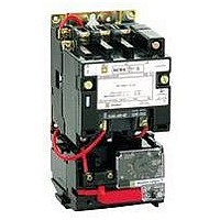
Manufacturer Part Number
8536SAG12V02S
Description
Magnetic Motor Starter
Manufacturer
SQUARE D
Datasheet
1.8502SEO2V02S.pdf
(54 pages)
Specifications of 8536SAG12V02S
No. Of Phases
Three
Power Rating
2hp
Current Rating
9A
Peak Reflow Compatible (260 C)
No
Supply Voltage Max
460VAC
Control Voltage Max
120V
Leaded Process Compatible
No
Switch Function
3PST
Supply Voltage Range
110VAC To 120VAC
Rohs Compliant
No
Contact Rating
9A
Lead Free Status / RoHS Status
Contains lead / RoHS non-compliant


NEMA
Size
00
0
1
1P
2
3
4
5
6f
7f
Tables and footnotes are taken from NEMA Standards.
j
t
a
u
k
f
The motor ratings in the above table are NEMA standard ratings and apply only when the code letter of the motor is the same as or occurs earlier in the alphabet than is shown in
the table below. Motors having code letters occurring later in the alphabet may require a larger controller. Consult local Square D field office.
Motor HP Rating
1
3-5
7
1
1
⁄
⁄
2
2
-2
& above
Ratings shown are for applications requiring repeated interruptions of stalled motor current or repeated closing of high transient currents encountered in rapid motor reversal, involving more
than five openings or closings per minute and more than ten in a ten-minute period, such as plug-stop, plug-reverse or jogging duty. Ratings apply to single speed and multi-speed
controllers.
Per NEMA Standards paragraph ICS 2-321.20, the service-limit current represents the maximum ms current, in amperes, which the controller may be expected to carry for protracted periods
in normal service. At service-limit current ratings, temperature rises may exceed those obtained by testing the controller at its continuous current rating. The ultimate trip current of over-
current (overload) relays or other motor protective devices shall not exceed the service-limit current ratings of the controller.
FLUORESCENT LAMP LOADS – 300 VOLTS AND LESS – The characteristics of fluorescent lamps are such that it is not necessary to derate Class 8502 contactors below their normal
continuous current rating. Class 8903 contactors may also be used with fluorescent lamp loads. For controlling tungsten and infrared lamp loads, and resistance heating loads, Class 8903
ac lighting contactors are recommended. These contactors are specifically designed for such loads and are applied at their full rating as listed in the Class 8903 Section.
Ratings apply to contactors which are employed to switch the load at the utilization voltage of the heat producing element with a duty which requires continuous operation of not more than
five openings per minute. Class 8903 Types L and S lighting contactors are rated for resistance heating loads.
When discharged, a capacitor has essentially zero impedance. For repetitive switching by contactor, sufficient impedance should be connected in series to limit inrush current to not more
than 6 times the contactor rated continuous current. In many installations, the impedance of connecting conductors may be sufficient for this purpose. When switching to connect additional
banks, the banks already on the line may be charged and can supply additional available short-circuit current which should be considered when selecting the impedance to limit the current.
The ratings for capacitor switching above assume the following maximum available fault currents: NEMA Size 2-3: 5,000 A RMS Sym.; NEMA Size 4-5: 10,000 A RMS Sym.; NEMA Size
6-7: 18,000 A RMS Sym. If available fault current is greater than these values, connect sufficient impedance in series as noted in the previous paragraph.
See Page 16 regarding operation rates for Size 6 & 7.
5/98
Load
Volts
115
200
230
380
460
575
115
200
230
380
460
575
115
200
230
380
460
575
115
230
115
200
230
380
460
575
115
200
230
380
460
575
200
230
380
460
575
200
230
380
460
575
200
230
380
460
575
230
460
575
Maximum
Horsepower
Rating –
Nonplugging
and
Nonjogging
Duty
Single
Phase
1
. . .
1
. . .
. . .
. . .
1
. . .
2
. . .
. . .
. . .
2
. . .
3
. . .
. . .
. . .
3
5
3
. . .
7
. . .
. . .
. . .
. . .
. . .
. . .
. . .
. . .
. . .
. . .
. . .
. . .
. . .
. . .
. . .
. . .
. . .
. . .
. . .
. . .
. . .
. . .
. . .
. . .
. . .
. . .
. . .
⁄
2
1
⁄
2
Poly-
Phase
. . .
1
1
1
2
2
. . .
3
3
5
5
5
. . .
7
7
10
10
10
. . .
. . .
. . .
10
15
25
25
25
. . .
25
30
50
50
50
40
50
75
100
100
75
100
150
200
200
150
200
300
400
400
300
600
600
1
1
1
1
1
⁄
⁄
⁄
⁄
⁄
2
2
2
2
2
Maximum Allowable Motor
Code Letter
L
K
H
Maximum
Horsepower
Rating –
Plugging and
Jogging Duty j
Single
Phase
. . .
. . .
. . .
. . .
. . .
. . .
1
. . .
1
. . .
. . .
. . .
1
. . .
2
. . .
. . .
. . .
1
3
2
. . .
5
. . .
. . .
. . .
. . .
. . .
. . .
. . .
. . .
. . .
. . .
. . .
. . .
. . .
. . .
. . .
. . .
. . .
. . .
. . .
. . .
. . .
. . .
. . .
. . .
. . .
. . .
. . .
⁄
2
1
⁄
2
Poly-
Phase
. . .
. . .
. . .
. . .
. . .
. . .
. . .
1
1
1
2
2
. . .
3
3
5
5
5
. . .
. . .
. . .
7
10
15
15
15
. . .
15
20
30
30
30
25
30
50
60
60
60
75
125
150
150
125
150
250
300
300
. . .
. . .
. . .
1
1
1
1
⁄
⁄
⁄
⁄
2
2
2
2
Continuous
Current
Rating,
Amperes –
600 Volt
Max.
9
9
9
9
9
9
18
18
18
18
18
18
27
27
27
27
27
27
36
36
45
45
45
45
45
45
90
90
90
90
90
90
135
135
135
135
135
270
270
270
270
270
540
540
540
540
540
810
810
810
© 1998 Square D All Rights Reserved
Service –
Limit
Current
Rating,
Amperes
t
11
11
11
11
11
11
21
21
21
21
21
21
32
32
32
32
32
32
42
42
52
52
52
52
52
52
104
104
104
104
104
104
156
156
156
156
156
311
311
311
311
311
621
621
621
621
621
932
932
932
Tungsten
and
Infrared
Lamp
Load,
Amperes –
250 Volts
Max.
a
5
5
5
. . .
. . .
. . .
10
10
10
. . .
. . .
. . .
15
15
15
. . .
. . .
. . .
24
24
30
30
30
. . .
. . .
. . .
60
60
60
. . .
. . .
. . .
120
120
. . .
. . .
. . .
240
240
. . .
. . .
. . .
480
480
. . .
. . .
. . .
. . .
. . .
. . .
Resistance
Heating Loads,
KW – Other
Than Infrared
Lamp Loads
u
Single
Phase
. . .
. . .
. . .
. . .
. . .
. . .
. . .
. . .
. . .
. . .
. . .
. . .
3
. . .
6
. . .
12
15
. . .
. . .
5
. . .
10
. . .
20
25
10
. . .
20
. . .
40
50
. . .
30
. . .
60
75
. . .
60
. . .
120
150
. . .
120
. . .
240
300
180
360
450
Poly-
Phase
. . .
. . .
. . .
. . .
. . .
. . .
. . .
. . .
. . .
. . .
. . .
. . .
5
9.1
10
16.5
20
25
. . .
. . .
8.5
15.4
17
28
34
43
17
31
34
56
68
86
45
52
86.7
105
130
91
105
173
210
260
182
210
342
415
515
315
625
775
Application Data – Class 8502, 8536
KVA Rating for Switching
Transformer Primaries at 50 or 60
Cycles
Transformers
Having Inrush
Currents (Worst
Case Peak) of
Not More Than
20 Times Peak of
Continuous
Current Rating
Single
Phase
. . .
. . .
. . .
. . .
. . .
. . .
0.6
. . .
1.2
. . .
2.4
3.0
1.2
. . .
2.4
. . .
4.9
6.2
. . .
. . .
2.1
. . .
4.1
. . .
8.3
10.0
4.1
. . .
8.1
. . .
16
20
. . .
14
. . .
27
34
. . .
27
. . .
54
68
. . .
54
. . .
108
135
. . .
. . .
. . .
Poly-
Phase
. . .
. . .
. . .
. . .
. . .
. . .
. . .
1.8
2.1
. . .
4.2
5.2
. . .
3.6
4.3
. . .
8.5
11.0
. . .
. . .
. . .
6.3
7.2
. . .
14
18
. . .
12
14
. . .
28
35
20
23
. . .
47
59
41
47
. . .
94
117
81
94
. . .
188
234
. . .
. . .
. . .
Transformers
Having Inrush
Currents (Worst
Case Peak) of
Over 20 Through
40 Times Peak of
Continuous
Current Rating
Single
Phase
. . .
. . .
. . .
. . .
. . .
. . .
0.3
. . .
0.6
. . .
1.2
1.5
0.6
. . .
1.2
. . .
2.5
3.1
. . .
. . .
1.0
. . .
2.1
. . .
4.2
5.2
2.0
. . .
4.1
. . .
8.1
10
. . .
6.8
. . .
14
17
. . .
14
. . .
27
34
. . .
27
. . .
54
68
. . .
. . .
. . .
Poly-
Phase
. . .
. . .
. . .
. . .
. . .
. . .
. . .
0.9
1.0
. . .
2.1
2.6
. . .
1.8
2.1
. . .
4.3
5.3
. . .
. . .
. . .
3.1
3.6
. . .
7.2
8.9
. . .
6.1
7.0
. . .
14
18
10
12
. . .
23
29
20
24
. . .
47
59
41
47
. . .
94
117
. . .
. . .
. . .
3 Phase
Rating for
Switching
Capacitors
k
KVAR
. . .
. . .
. . .
. . .
. . .
. . .
. . .
. . .
. . .
. . .
. . .
. . .
. . .
. . .
. . .
. . .
. . .
. . .
. . .
. . .
. . .
. . .
8
. . .
16
20
. . .
. . .
27
. . .
53
67
. . .
40
. . .
80
100
. . .
80
. . .
160
200
. . .
160
. . .
320
400
240
480
600
13
Related parts for 8536SAG12V02S
Image
Part Number
Description
Manufacturer
Datasheet
Request
R


Part Number:
Description:
Pushbutton, Non-Illum'd Red "STOP", Momentary, 1NO-1NC, Square 30mm, 10A, 600V
Manufacturer:
SQUARE D
Datasheet:
Part Number:
Description:
CB ACCESSORY, UNDERVOLTAGE TRIP 48V DC
Manufacturer:
SQUARE D
Datasheet:
Part Number:
Description:
CB ACCESSORY, TRIP UNIT
Manufacturer:
SQUARE D
Datasheet: