MM-PENTRA-24-HG1F IDEC, MM-PENTRA-24-HG1F Datasheet - Page 26
MM-PENTRA-24-HG1F
Manufacturer Part Number
MM-PENTRA-24-HG1F
Description
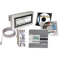
PLC Solution Package
Manufacturer
IDEC
Datasheet
1.FC4A-HPC1.pdf
(44 pages)
Specifications of MM-PENTRA-24-HG1F
Kit Contents
4.6" HG1F Monochrome STN Touchscreen Operator Interface, 24 I/O All-in-one CPU, 30W Power Supply, WindO/I-NV2 Software, XWIE E-stop & Name Plate, PC Cable
Lead Free Status / RoHS Status
Lead free / RoHS Compliant


26
All-in-One
Part Number
Control System
Instruction Words
Program Capacity
User Program Storage
Processing
Time
Expandable I/O Module
I/O Points
Internal Relay
Shift Register
Data Register
Extra Data Register
Counter
Timer (1-sec, 100-ms, 10-ms, 1-ms)
Self-diagnostic Function
Input Filter
Catch Input/Interrupt Input
Analog
Potentiometer
Analog
Voltage Input
Pulse
Output
Sensor Power
Supply
(AC Power Only)
Port 1
Port 2 Communication Adapter (option)
Clock Cartridge (option)
Memory Cartridge (option)
HMI Module (option)
1. 1 step equals 6 bytes.
2. Not including expansion I/O service time, clock function processing time, data link processing time, and interrupt processing time.
3. Maintenance communication, user communication, Modem communication, datalink, Modbus master/slave communication (FC5A only).
Note: The maximum number of relay outputs that can be turned on simultaneously is 33 including those on the CPU module.
Backup Data
Backup Duration
Battery
Charging Time
Battery Life
Replaceability
Maximum Counting
Frequency and High-speed
Counter Points
Counting Range
Operation Mode
1
Basic Instruction
END Processing
Input
Output
Number
Input Voltage Range
Input Impedance
Data Range
Number
Max. Frequency
Number
Data Range
Output Voltage
Current
Overload
Detection
Isolation
MicroSmart Series
2
3
FC5A-C10R2
FC5A-C10R2C
76 advanced
13.8 KB (2,300 steps)
0.64ms
—
6
4
1 point
Possible
Possible
Possible
Possible
Power failure, watchdog timer, data link connection, user program EPPROM sum check, timer/counter preset value sum check, user program
RAM sum check, keep data, user program syntax, user program writing, CPU module, clock IC, I/O bus initialize, user program execution
Single/two-phase selectable: 50KHz (1 point)
Single-phase: 5KHz (3 points)
1.16ms (1,000 steps)
FC5A-C16R2
FC5A-C16R2C
76 advanced
27 KB (4,500 steps)
9
7
Possible
Possible
Possible
Possible
Total 4 points
2,048 points
2,000 points
128 points
256 points
256 points
—
Approx. 30 days (typical) at 25ºC after backup battery fully charged
Without fi lter or 3 to 15ms fi lter (selectable in increments of 1ms)
www.idec.com
Approx. 15 hours for charging from 0% to 90% of full charge
RS232C (maintenance communication, user communication)
Internal relay, shift register, counter, data register
Rotary encoder mode and adding counter mode
Minimum turn off pulse width: 150μs minimum
Minimum turn on pulse width: 40μs minimum
FC5A-C24R2
FC5A-C24R2C
81 advanced
54 KB (9,000 steps)
4 modules
14
10
2 points
Possible
Possible
Possible
Possible
EEPROM (10,000 times rewritable)
24V DC (+10% to -15%), 250mA
Isolated from the internal circuit
Lithium secondary battery
Four inputs (I2 through I5)
Expansion:
64
Stored program system
0 to 65535 (16 bits)
35 basic
0 to 255
5 years
N/A
N/A
—
—
FC4A-C10R2
FC4A-C10R2C
38 advanced
4.8 KB (800 steps)
0.64ms
—
6
4
256 points
64 points
400 points
—
32 points
32 points
1 point
—
Possible
Possible
Possible
Programmable Logic Controllers
Single/two-phase selectable: 20KHz (1 point)
Single-phase: 5KHz (3 points)
FC4A-C16R2
FC4A-C16R2C
40 advanced
15 KB (2,500 steps)
9
7
Possible
Possible
Possible
Possible
1.65ms (1,000 steps)
Total 4 points
1,024 points
1,300 points
128 points
100 points
100 points
FC4A-C24R2
FC4A-C24R2C
46 advanced
27 KB (4,500 steps)
4 modules
14
10
2 points
Possible
Possible
Possible
Possible
Expan-
sion: 64
Related parts for MM-PENTRA-24-HG1F
Image
Part Number
Description
Manufacturer
Datasheet
Request
R

Part Number:
Description:
STARTER KIT 5.7 HG2G COLOR PLC PENTRA 16I/O
Manufacturer:
IDEC Corporation
Datasheet:
Part Number:
Description:
STARTER KIT 5.7 HG2G MONOCHROME PLC PENTRA 16I/O
Manufacturer:
IDEC Corporation
Datasheet:
Part Number:
Description:
MM-PENTRA-16-HG2G-C12V
Manufacturer:
IDEC
Datasheet:
Part Number:
Description:
MM-PENTRA-16-HG2G-EC12V
Manufacturer:
IDEC
Datasheet:

Part Number:
Description:
MM-PENTRA-16-HG2G-EM12V
Manufacturer:
IDEC
Datasheet:
Part Number:
Description:
MM-PENTRA-16-HG2G-M12V
Manufacturer:
IDEC
Datasheet:
Part Number:
Description:
Starter Kit, FC5A-C24R2, input simular switch, screwdriver, cable, software
Manufacturer:
IDEC Corporation
Datasheet:
Part Number:
Description:
Starter Kit, FC5A-D16RS1, 30W powersupply, screwdriver, cable, software
Manufacturer:
IDEC Corporation
Datasheet:
Part Number:
Description:
STARTER KIT 5.7 HG2G COLOR PLC PENTRA 24I/O
Manufacturer:
IDEC Corporation
Datasheet:
Part Number:
Description:
Starter Kit, 16 I/O MicroSmart Pentra, HG1B O/I, Power Supply, Software, Cable
Manufacturer:
IDEC Corporation
Datasheet:

Part Number:
Description:
Starter Kit - 12I/O Pentra CPU W/Ethernet, 30W Power Supply, USB Cable, And Software
Manufacturer:
IDEC
Datasheet:

Part Number:
Description:
PLC Starter Kit
Manufacturer:
IDEC
Datasheet:

Part Number:
Description:
PLC Solution Package
Manufacturer:
IDEC
Datasheet:

Part Number:
Description:
PLC Solution Package
Manufacturer:
IDEC
Datasheet:
Part Number:
Description:
Starter Kit; UL Listed, CE Certified
Manufacturer:
IDEC Corporation
Datasheet: