WM14-96AV53CS CARLO GAVAZZI, WM14-96AV53CS Datasheet - Page 2
WM14-96AV53CS
Manufacturer Part Number
WM14-96AV53CS
Description
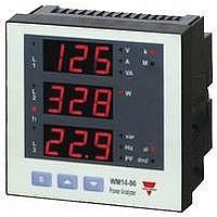
POWER ANALYZER
Manufacturer
CARLO GAVAZZI
Datasheet
1.WM14-96AV53CS.pdf
(6 pages)
Specifications of WM14-96AV53CS
Meter Function
Power Analyzer / Energy Management
Power Consumption
4W
Operating Temperature Range
0°C To +50°C


RS485 Serial
Power Supply Specifications
Auxiliary power supply
WM14-96
Software functions
Password
System selection
Transformer ratio
Filter
Displaying
Operating
temperature
Storage
temperature
Installation category
Insulation (for 1 minute)
RS422/RS485 (on
2
General Specifications
CT
VT
Operating range
Filtering coefficient
Filter action
3-phase system with neutral
Type
Connections
Addresses
Protocol
1st level
2nd level
request)
Port Specifications
Up to 3 variables per page
Page 1: V L1, V L2, V L3
Page 2: V L12, V L23, V L31
Numeric code of max. 3
digits; 2 protection levels
of the programming data
Password “0”, no
protection
Password from 1 to 999,
all data are protected
3-phase with/without n, unbal.
3-phase balanced
3-phase ARON
2-phase
Single phase
1 to 999
1.0 to 99.9
0 to 99.9% of the input
electrical scale
1 to 16
Measurements, alarms,
serial output (fundamental
variables: V, A, W and their
derived ones).
230VAC
-15 +10%, 50-60Hz
115VAC
-15 +10%, 50-60Hz
48VAC
-15 +10%, 50-60Hz
0° to +50°C (32° to 122°F)
(RH < 90% non condensing)
-10° to +60°C (14° to 140°F)
(RH < 90% non condensing)
Cat. III (IEC 60664, EN60664)
4kVAC, 500VDC
between measuring
inputs and power supply.
500VAC/DC between
Multidrop
bidirectional (static and
dynamic variables)
2 or 4 wires, max. distance
1200m, termination directly
on the instrument
1 to 255, key-pad selectable
MODBUS/JBUS
Specifications
Alarms
Reset
Power consumption
Dielectric
EMC
Data
Data format
Baud-rate
Emissions
(bidirectional)
Dynamic (reading only)
Static (writing only)
strength
are subject to change without notice
Page 3:
Page 4: A L1 dmd, A L2 dmd,
Page 5: An, An Alarm
Page 6: W L1, W L2, W L3
Page 7: PF L1, PF L2, PF L3
Page 8: var L1, var L2, var L3
Page 9: VA L1, VA L2, VA L3
Page 10: VA , W , var
Page 11: VA dmd, W dmd, Hz
Page 12: W dmd max
Page 13: Wh
Page 14: varh
Page 15: VL-L , PF ,
Page 18: working hours
Programmable, for the V
An (neutral current).
Note: the alarm is only visual,
by means of LED on the front
of the instrument.
Independent alarm (VL
Page 16: A max
Page 17: A dmd max
max: A dmd, W dmd
all counters (Wh, varh, h)
24VAC
-15 +10%, 50-60Hz
18 to 60VDC
AC: 4.5
DC: 4W
System, phase variables and
energies
All configuration parameters
1 start bit, 8 data bit,
no parity, 1 stop bit.
9600 bit/s
measuring inputs and RS485.
4kVAC, 500VDC between
power supply and RS485
4kVAC (for 1 min)
EN50084-1 (class A)
residential environment,
commerce and light industry
VA
A L3 dmd
VLN Alarm
A L1, A L2, A L3
WM14-96DS0904
LN
, An)
and
Related parts for WM14-96AV53CS
Image
Part Number
Description
Manufacturer
Datasheet
Request
R

Part Number:
Description:
WM14-96 ADV., 3-PHASE MULTI-FUNCTION METERS, 120/208VLL, 90-260VAC/DC, 2-RELAY
Manufacturer:
CARLO GAVAZZI
Part Number:
Description:
WM14-96 BSC, 3-PHASE MULTI-FUNCTION METERS, 280/660VLL, 24VAC, GALV. INS. INPUTS + PULSE
Manufacturer:
CARLO GAVAZZI
Part Number:
Description:
WM14-96 BSC, 3-PHASE MULTI-FUNCTION METERS, 280/660VLL, 24VAC, GALV. INS. INPUTS + RS485
Manufacturer:
CARLO GAVAZZI
Part Number:
Description:
WM14-96 BSC, 3-PHASE MULTI-FUNCTION METERS, 280/660VLL, 48VAC, GALV. INS. INPUTS + PULSE
Manufacturer:
CARLO GAVAZZI
Part Number:
Description:
WM14-96 BSC, 3-PHASE MULTI-FUNCTION METERS, 280/660VLL, 48VAC, GALV. INS. INPUTS + RS485
Manufacturer:
CARLO GAVAZZI
Part Number:
Description:
WM14-96 BSC, 3-PHASE MULTI-FUNCTION METERS, 280/660VLL, 115VAC, GALV. INS. INPUTS + PULSE
Manufacturer:
CARLO GAVAZZI
Part Number:
Description:
WM14-96 BSC, 3-PHASE MULTI-FUNCTION METERS, 280/660VLL, 230VAC, GALV. INS. INPUTS + PULSE
Manufacturer:
CARLO GAVAZZI
Part Number:
Description:
WM14-96 BSC, 3-PHASE MULTI-FUNCTION METERS, 280/660VLL, 230VAC, GALV. INS. INPUTS + RS485
Manufacturer:
CARLO GAVAZZI
Part Number:
Description:
WM14-96 ADV., 3-PHASE MULTI-FUNCTION METERS, 380/660VLL, 90-260VAC/DC, 2 OPEN COLL., RS485 PRT
Manufacturer:
CARLO GAVAZZI
Part Number:
Description:
WM14-96 ADV., 3-PHASE MULTI-FUNCTION METERS, 380/660VLL, 90-260VAC/DC, 2 OPEN COLL.
Manufacturer:
CARLO GAVAZZI
Part Number:
Description:
MAGNETIC CYLINDRICAL PROX. SENSOR
Manufacturer:
CARLO GAVAZZI
Datasheet:
Part Number:
Description:
CYLINDRICAL MAGNETIC SENSOR
Manufacturer:
CARLO GAVAZZI
Datasheet:
Part Number:
Description:
MAGNETIC CYLINDRICAL PROX. SENSOR
Manufacturer:
CARLO GAVAZZI
Datasheet: