4501 DIGITRON, 4501 Datasheet - Page 2
4501
Manufacturer Part Number
4501
Description
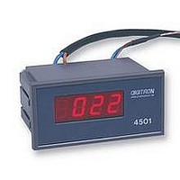
DPM, THERMOMETER TYPE K
Manufacturer
DIGITRON
Datasheet
1.4801J.pdf
(2 pages)
Specifications of 4501
Meter Function
Thermometer
Meter Range
-50°C To +700°C
Digit Height
11.2mm
Supply Voltage Range
216.2VAC To 253VAC
Operating Temperature Range
0°C To +45°C
External Depth
68.1mm
Accuracy %
0.5%
Available stocks
Company
Part Number
Manufacturer
Quantity
Price

Part Number:
4501
Manufacturer:
ON/安森美
Quantity:
20 000
Part Number:
4501SS
Manufacturer:
GTM
Quantity:
20 000


HYSTERESIS
(MODELS 4801, 4804)
The hysteresis is factory preset to ±2 counts. It should only be adjusted
by qualified and trained staff, and using a small insulated screwdriver as
indicated in Figure 1.
It should not be carried out while the instrument is powered up.
Hysteresis may be adjusted by ±1 count up to ±10 counts.
PANEL FITTING
The instrument is designed to fit in a panel cut out measuring 92 x 45mm.
The panel should be between 1.5 and 3.5mm thick.
The instrument is fitted by sliding into the aperture and pressing firmly
home into position.
REMOVAL
Before the instrument can be removed from the panel, the connectors
must
1.
2.
3.
REMOVAL OF PCB FROM CASE
Follow instructions for removal. Tap instrument (face down) into the palm
of the hand. If it does not slide out it can be pushed out by gentle
pressure from the rear on the terminal pins. Do
prise out the PCB.
Ensure that the power is disconnected.
Remove the front window by gently levering with a small screwdriver
on the slot on the lower edge of the window.
Use a screwdriver to release the clamping arms by slightly bending
back the lugs as shown below, whilst gently pulling the instrument
forward.
be unplugged from the rear of the panel.
not
use a screwdriver to
NB: The rear cover should always be fitted.
WIRING
All connections should be made using the supplied terminal plugs only,
and these slide on to the appropriate terminal pins. Detailed connections
are given on the rear of the instrument and these drawings should be
used in conjunction with the following instructions.
Note:
ALARMS
(MODELS 4801, 4804)
These models have a relay fitted and the alarm point can be adjusted
from the front panel.
SET POINT ADJUSTMENT
Hold in the set point button and adjust the set point potentiometer for the
required number of counts as indicated by the display.
RELAY CONNECTIONS
These instruments have a control relay with a rating of 5A at 250V a.c.,
and 30V d.c. for resistive loads.
Connection is shown on the rear label and should be made using the
supplied terminal block.
These ratings should not be exceeded and an external contactor should
be used for high power or 3 phase requirements.
PLATINUM RESISTANCE SENSORS
(MODELS 4504, 4804)
The sensor should be connected to the instrument using a four core
copper cable as shown below:
Standard Pt100 sensor identification colours:
When refitting the plugs, ensue that this is done correctly.
N.C
Yellow
Black
.
COM N.O.
Pt100
A
B
4504/4804
Red
Blue
A B C D
When relay is not energised:
N.C. = Normally Closed
COM = Common
N.O. = Normally Open
C
D
USING 3 WIRE SENSORS
These should be connected as per the 2 wire sensors, but with terminal
A+B and C+D linked.
THERMOCOUPLES
(MODELS 4501, 4801)
Thermocouples should, if possible, be wired directly into the terminal
block taking care to observe the correct polarity.
If the thermocouple has to be extended, this should only be carried out by
using extension or compensating cable of a type appropriate to the
thermocouple being used.
NOTE:
affected by the type of cable.
The accuracy may be affected by cable lengths. This is also
Thermocouple
4501/4801
A
B C D
+ve
-ve
Related parts for 4501
Image
Part Number
Description
Manufacturer
Datasheet
Request
R

Part Number:
Description:
PROBE, GENERAL PURPOSE
Manufacturer:
DIGITRON
Datasheet:

Part Number:
Description:
PROBE, SURFACE
Manufacturer:
DIGITRON
Datasheet:

Part Number:
Description:
TEMPERATURE CONTROLLER, J, T/C
Manufacturer:
DIGITRON
Datasheet:
Part Number:
Description:
TEMPERATURE CONTROLLER, K, T/C
Manufacturer:
DIGITRON
Datasheet:
Part Number:
Description:
TEMPERATURE CONTROLLER, PT100
Manufacturer:
DIGITRON
Datasheet:

Part Number:
Description:
DPM, THERMOMETER PT100
Manufacturer:
DIGITRON
Datasheet:
Part Number:
Description:
SILICON PROGRAMMABLE UNIJUNCTION TRANSISTORS 40 VOLTS 250mW
Manufacturer:
Digitron
Part Number:
Description:
Silicon Controlled Rectifier
Manufacturer:
Digitron Electronic
Datasheet:

Part Number:
Description:
WiFi / 802.11 Modules & Development Tools TiWi01-R2 Module with U.FL Connector
Manufacturer:
LS Research
Datasheet:
Part Number:
Description:
Conn Unshrouded Header HDR 30 POS 2.54mm Solder ST Thru-Hole
Manufacturer:
Precidip
Part Number:
Description:
DEV KIT, PROFLEX01-R2 F ANTENNA
Manufacturer:
LS Research
Datasheet:
Part Number:
Description:
TIWI5 MODULE, ROHS
Manufacturer:
LS Research
Datasheet: