VS1-H233-00-CE Emerson Network Power, VS1-H233-00-CE Datasheet - Page 5
VS1-H233-00-CE
Manufacturer Part Number
VS1-H233-00-CE
Description
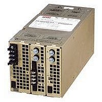
POWER SUPPLY, SWITCH MODE, 5V
Manufacturer
Emerson Network Power
Datasheet
1.VS1-A2-H335-00-CE.pdf
(8 pages)
Specifications of VS1-H233-00-CE
Power Supply Type
Switching
Power Supply Output Type
Fixed
No. Of Outputs
3
Output Voltage
5V
Output Current
400A
Power Rating
500W
Input Voltage
85V AC To 264V AC
Length
279.31mm
Width
127.03mm
Lead Free Status / RoHS Status
Contains lead / RoHS non-compliant


VS1 & VS6 • 1000-1500 WATTS
NOTES (ALL MODELS)
1. Input: Barrier type. Three No. 6-32 B.H. screws (0.375” centers). For VS1, VS3 & VS4 additional GND CONN added for VS6, VS8 & VS9.
2. Control connectors: (J1 and J2) 10 position Molex 90130-3210 housing, gold plated contacts. Mates with Molex 90142-0010 housing with
3. Output terminals (A-300 W) (B-600 W) & (K-750 W) single modules: two (2) 10-32 UNF HEX HD BOLTS. Max. torque: 25 in-lbs (2.78 N-m).
4. Output terminals (E/F-250 W) & (G/H-500 W) dual/triple modules: Primary: two (2) 10-32 UNF HEX HD BOLTS. Max. torque: 25 in-lbs (2.78 N-m).
5. Output terminals (C-900 W) (D-1200 W) & (L-1500 W) single modules: four 5/16-18 x 5/8" hex head cap screws. Max. torque: 120 in-lbs
6. Chassis material: aluminum with chemical film coating.
7. Adjustment access: voltage, power fail, and overcurrent from front panel.
8. Bar code: code 39 extended.
9. Mounting for 5-inch & 8-inch case: four(4) 8-32 clinch nuts on three (3) surfaces.
10. Additional support is recommended when unit is mounted in a suspended configuration.
11. Fans:
12. All dimensions are in inches (mm).
13. Specifications subject to change without notice.
Drawings
Max torque: 10 in-lbs (1.1 N-m).
90119-2110 crimp contacts (Molex C - Grid III Series). Connector kit includes mating connector and 10 pins, Astec part #70-841-004.
Secondary: barrier strip two (2) 6-32 UNC screws (0.375” centers) per output. Max torque: 10 in-lbs (1.1 N-m).
(13.35 N-m). Captive lock washer provided.
Mounting for 11-inch case:
Mounting clinch nuts are not designed to support the weight of the unit.
5
5-inch Case Size (5” x 5” x 11”)
(51.82 ± 1.27)
(171.45 ± .50)
(19.05 ± 1.27)
Input
Module
6.750 ± .020
5-inch case, (1) 4.5" dia, 112 CFM (no load), 49 dBA.
8-inch case, (1) 4.5" dia, 112 CFM (no load), 49 dBA; (2) 2.25” dia, 23 CFM (no load), 38 dBA.
11-inch case, (2) 4.5" dia, 112 CFM (no load), 49dBA
.750 ± .050
2.04 ± .05
Americas: (760) 930-4600
AC High
Neutral
Ground
J1
(88.65 ± 1.27)
3.49 ± .05
5.00 ± 0.05
VS1
four (4) 8-32 clinch nuts on two (2) side surfaces &
six (6) 8-32 clinch nuts on bottom surface.
Max. penetration 0.150 inch (3.81). Max. torque: 15 in-lbs (1.67 N-m).
(101.60 ± .50)
4.000 ± .020
AC Main Input
Technical Support: (888) 41-ASTEC or (407) 241-2752
Bottom
(127.03)
5.00
Europe (UK) 44 (1384) 842-211
(12.70 ± 1.27)
.500 ± .050
Max
8-32 UNC-2B
Threaded Insert,
4 Places
Max penetration:
0.150 (3.81)
23.89)
.94
MAX
Side
Back
(279.31 ± 1.27)
11.00 ± .05
Asia (HK) 852-2437-9662
(51.82 ± 1.27)
Input
Module
(171.45 ± .50)
2.04 ± .05
6.750 ± .020
AC Phase B
AC Phase C
AC Phase A
AC Ground
STD AIR FLOW
(6.86 ± 1.27)
.27 ± .05
J1
(88.65 ± 1.27)
N
3.49 ± .05
5.00 ± 0.05
VS6
8-32 UNC-2B
Threaded Insert, 4 Places
Like Pattern Opposite Side
Max penetration: 0.150 (3.81 )
(19.05 ± 1.27)
1.2
.750 ± .050
(101.60 ± .50)
(12.70 ± 1.27)
4.000 ± .020
.500 ± .050
(127.03)
5.00
Max
69-825-410 Rev C
12.01.04
Related parts for VS1-H233-00-CE
Image
Part Number
Description
Manufacturer
Datasheet
Request
R

Part Number:
Description:
AC/DC Front end 12Vo 36A 12Vsb Standard Airflow
Manufacturer:
Emerson Network Power

Part Number:
Description:
POWER SUPPLY SGL 5VOUT 40W 3X5"
Manufacturer:
Emerson Network Power
Datasheet:

Part Number:
Description:
POWER SUPPLY DIN 24VDC 10A
Manufacturer:
Emerson Network Power
Datasheet:

Part Number:
Description:
POWER SUPPLY SGL 48VOUT 40W 3X5"
Manufacturer:
Emerson Network Power
Datasheet:

Part Number:
Description:
POWER SUP MED&ITE 48V 45W 2"X4"
Manufacturer:
Emerson Network Power
Datasheet:

Part Number:
Description:
POWER SUPPLY 60W 12V OUT
Manufacturer:
Emerson Network Power
Datasheet:

Part Number:
Description:
POWER SUPPLY 60W 48V OUT
Manufacturer:
Emerson Network Power
Datasheet:

Part Number:
Description:
POWER SUPPLY 60W 15V OUT
Manufacturer:
Emerson Network Power
Datasheet:

Part Number:
Description:
POWER SUPPLY TRPL 3.3/5/12V 40W
Manufacturer:
Emerson Network Power
Datasheet:

Part Number:
Description:
POWER SUPPLY SWITCHER 24V 40W
Manufacturer:
Emerson Network Power
Datasheet:

Part Number:
Description:
Linear & Switching Power Supplies 24V output 25W 2A Medical &Non-Medical
Manufacturer:
Emerson Network Power
Datasheet:
Part Number:
Description:
Linear & Switching Power Supplies 50W +5/+12/-12VDC
Manufacturer:
Emerson Network Power
Datasheet:
Part Number:
Description:
Linear & Switching Power Supplies 150W 48V 2.1A
Manufacturer:
Emerson Network Power
Datasheet:

Part Number:
Description:
Linear & Switching Power Supplies 600W 24V 0-27A MAX 2.4 x 4.5 x 7.5
Manufacturer:
Emerson Network Power
Datasheet: