AP12-1-72-203 AIRPAX, AP12-1-72-203 Datasheet - Page 6
AP12-1-72-203
Manufacturer Part Number
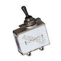
AP12-1-72-203
Description
CIRCUIT PROTECTOR, HYD-MAG, 2P, 240V 20A
Manufacturer
AIRPAX
Series
APr
Datasheet
1.AP112-1R-36616-3.pdf
(12 pages)
Specifications of AP12-1-72-203
Input Voltage Vac
240V
No. Of Poles
2
Current Rating
20A
Interrupting Capacity
1kA
Dielectric Strength
1250Vrms
Trip Time
9s
Voltage Rating Vdc
50V
Trip Time Max
9sec
Leaded Process Compatible
No
Rohs Compliant
No
Lead Free Status / RoHS Status
Contains lead / RoHS non-compliant


81
CONFIGURATIONS
Series Trip
The most popular configuration for magnetic protectors is the
series trip where the sensing coil and contacts are in series
with the load being protected. The handle position conveniently
indicates circuit status. In addition to providing conventional
overcurrent protection, it’s simultaneously used as a power
disconnect.
Shunt Trip
The shunt trip is designed for controlling two separate loads
with one assembly. The control is established by providing
overload protection for the critical load. When the current
through this load becomes excessive and reaches the trip
point the protector will open and remove power from both
loads simultaneously. The total current rating of both loads
must not exceed the maximum contact rating.
Relay Trip
This permits the overload sensing coil to be placed in a circuit
which is electrically isolated from the trip contacts. The coil may
be actuated by sensors monitoring pressure, flow,
temperature, speed, etc. Other typical applications include
crowbar, interlock and emergency/rapid shutdown circuitry.
Trip may be accomplished by voltage or current, which must
be removed immediately upon tripping.
Remote Indication, AP1-1R
AP series trip circuit protectors are available with electrically
isolated contacts which are rated at 1/2 ampere, 120 volts AC
or 50 volts DC. These contacts provide SPDT switching action
which can be used to indicate “power-on” and “power-off”
conditions or to actuate lights, alarms or timing devices.
Voltage Trip
Sometimes called “dump circuits” or “panic trip circuits,”
these units make it possible to open main power contacts with
lower power inputs from one or more sources. This
configuration is becoming increasingly more important for
sensitive circuitry and denser packaging in automation
systems. Available in series, shunt or relay configurations.
AP/UP, AP/MIL Series - Configurations
[
11.13
UP1-1
(UL Recognized
Series)
Shunt Trip
AP1- 3
.438
Series with Auxiliary Switch
AP1-1R (Note A)
AP7-1 (Screw Terminal with Terminal Block)
Series Trip
AP1-1
NO
Note: Tolerance ± .031 [.79] Angles: ±5° unless noted.
]
C
NC
6 - 32 x .187 4.75
SCREW
NO. 6 LOCKWASHER
Dimensions in brackets [ ] are millimeters.
A. Main protector contacts open.
[
]
1.562 MAX.
39.67
NC
NO
C
]
]
SINGLE POLE
1.780 45.21
MAX.
MULTIPOLE
1.950 49.53
MAX.
Relay Trip (Note A)
AP1-4 (Relay)
Optional Booted
Terminals
SCHEMATIC
DIAGRAM
]
]
http://airpax.sensata.com/
]
]
]
.130
]
7.92
3.30
[
.312
11.13
.438
Switch with Auxiliary Switch
AP1-1RC (Note A)
NO
2X
RUBBER BOOT
±.010
]
±.25
]
DIM. FROM
BACK OF
PANEL.
]
22.22
.875
]
C
NC
]
]
.076
1.93
±.010
±.25
]
BOOT REMOVED
FOR CLARITY
]
1.350
34.29
DIA.
]
1.012
25.70
±.050
±1.27
NC
NO
C
]
]
7
Related parts for AP12-1-72-203
Image
Part Number
Description
Manufacturer
Datasheet
Request
R

Part Number:
Description:
FULLY SEALED MAGNETIC CIRCUIT
Manufacturer:
Sensata Technologies/Airpax
Datasheet:

Part Number:
Description:
CIRCUIT PROTECTOR, HYD-MAG, 2P, 240V 10A
Manufacturer:
AIRPAX
Datasheet:
Part Number:
Description:
CIRCUIT PROTECTOR, HYD-MAG, 2P, 240V 15A
Manufacturer:
AIRPAX
Datasheet:
Part Number:
Description:
CIRCUIT PROTECTOR, HYD-MAG, 2P, 240V, 5A
Manufacturer:
AIRPAX
Datasheet:

Part Number:
Description:
Circuit Breaker Magnetic Circuit Protectors 2Pole 15A 240VAC 4-Pin
Manufacturer:
AIRPAX
Datasheet:
Part Number:
Description:
FULLY SEALED MAGNETIC CIRCUIT
Manufacturer:
Sensata Technologies/Airpax
Datasheet:

Part Number:
Description:
Ap/up, Ap/mil Series Magnetic Circuit Protectors
Manufacturer:
Sensata Technologies
Datasheet:
Part Number:
Description:
Ap/up, Ap/mil Series Magnetic Circuit Protectors
Manufacturer:
Sensata Technologies
Datasheet: