NTE5125A NTE ELECTRONICS, NTE5125A Datasheet - Page 3
NTE5125A
Manufacturer Part Number
NTE5125A
Description
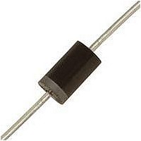
ZENER DIODE, 5W, 10V, AXIAL
Manufacturer
NTE ELECTRONICS
Datasheet
1.NTE5161A.pdf
(3 pages)
Specifications of NTE5125A
Zener Voltage Vz Typ
10V
Power Dissipation Pd
5W
Operating Temperature Range
-65°C To +200°C
No. Of Pins
2
Diode Type
Zener
Lead Free Status / RoHS Status
Lead free / RoHS Compliant


Electrical Characteristics (Cont’d): (T
Note 1 Test conditions for zener voltage and impedance are as follows: I
Note 2 Surge current is specified as the maximum allowable peak, non–recurrent square–wave cur-
Note 3 Test conditions for voltage regulation are as follows: V
NTE5159A
NTE5160A
NTE5161A
NTE5162A
NTE5163A
NTE5164A
NTE5165A
NTE5166A
to reading. Mounting contacts are located 3/8” to 1/2” from the inside edge of mounting clips
to the body of the diode (T
rent with a pulse width, PW, of 8.3ms. Mounting contact located as specified in Note 1.
and then at 50% of the I
current time duration for each V
ing contact located as specified in Note 1.
V
Nominal
(Note 1)
Voltage
Z
Zener
Volts
130
140
150
160
170
180
190
200
@ I
ZT
.040 (1.02) Dia
Current
Test
mA
I
10
ZT
8
8
8
8
5
5
5
Z
(25.4)
1.000
ZT
(Note1)
190
230
330
350
380
430
450
480
Max Zener Impedance
@ I
Z
max value listed in the “Electrical Characteristic” table. The test
A
ZT
= +25 C +8 , –2 C).
Color Band Denotes Cathode
Z
Z
ZK
A
measurement is 40 10ms (T
@ I
= +25 C unless otherwise specified)
(Note 1)
1250
1500
1500
1650
1750
1750
1850
1850
ZK
= 1mA
(9.41)
.370
Leakage Current
0.5
0.5
0.5
0.5
0.5
0.5
0.5
0.5
Max Reverse
I
A
R
@ V
Volts
98.8
106
122
129
137
144
152
114
R
Z
measurements are made at 10%
Max Surge
A
(Note 2)
Current
Amps
.204 (5.19) Dia
= +25 C +8 , –2 C). Mount-
1.2
1.2
1.1
1.1
0.9
0.9
Z
i
1
1
r
is applied 40 10ms prior
Regulation
(Note 3)
Voltage
Max
Volt
2.5
2.5
V
3
3
3
4
5
5
Z
Regulator
Current
Max
36.6
31.6
29.4
26.4
23.6
mA
I
34
28
25
ZM
Related parts for NTE5125A
Image
Part Number
Description
Manufacturer
Datasheet
Request
R

Part Number:
Description:
TRANSISTOR - NPN HIGH VOLTAGE HIGH SPEED SWITCHING
Manufacturer:
NTE ELECTRONICS
Datasheet:
Part Number:
Description:
NTE Zener Diode, Nominal Zener Voltage: 6.8 V, Zener Test Current: 5 MA, Reverse Current: 100 NA AT 3 V, Typical Differential Resistance: 8 Ohm, Typical Temperature Coefficient: 3 MV/K, Typical Diode Capacitance: 105 PF
Manufacturer:
NTE ELECTRONICS
Part Number:
Description:
NTE Zener Diode, Nominal Zener Voltage: 12 V, Zener Test Current: 5 MA, Reverse Current: 100 NA AT .7 VZnom, Typical Differential Resistance: 10 Ohm, Typical Temperature Coefficient: 8.4 MV/K, Typical Diode Capacitance: 65 PF
Manufacturer:
NTE ELECTRONICS

Part Number:
Description:
ZENER DIODE,SINGLE, TWO TERMINAL,100V V(Z),DO-41
Manufacturer:
NTE ELECTRONICS
Datasheet:


Part Number:
Description:
ZENER DIODE,SINGLE, TWO TERMINAL,5.6V V(Z),5%,DO-27
Manufacturer:
NTE ELECTRONICS

Part Number:
Description:
ZENER DIODE, 5W, 6.2V, AXIAL
Manufacturer:
NTE ELECTRONICS
Datasheet:

Part Number:
Description:
ZENER DIODE, 5W, 12V, AXIAL
Manufacturer:
NTE ELECTRONICS
Datasheet:
Part Number:
Description:
ZENER DIODE,SINGLE, TWO TERMINAL,15V V(Z),5%,DO-204AE
Manufacturer:
NTE ELECTRONICS