NTE5485 NTE ELECTRONICS, NTE5485 Datasheet
NTE5485
Manufacturer Part Number
NTE5485
Description
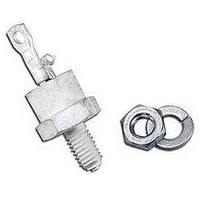
SCR THYRISTOR, 8A, 400V, TO-64
Manufacturer
NTE ELECTRONICS
Datasheet
1.NTE5485.pdf
(3 pages)
Specifications of NTE5485
Peak Repetitive Off-state Voltage, Vdrm
400V
Gate Trigger Current Max, Igt
30mA
Current It Av
8A
On State Rms Current It(rms)
8A
Peak Non Rep Surge Current Itsm 50hz
100A
Lead Free Status / RoHS Status
Lead free / RoHS Compliant


Description:
The NTE5480 through NTE5487 are multi−purpose PNPN silicon controlled rectifiers in a TO64 type
package suited for industrial and consumer applications. These 8 amp devices are available in volt-
ages ranging from 25V to 600V.
Features:
D Uniform Low−Level Noise−Immune Gate Triggering: I
D Low Forward “ON” Voltage: v
D High Surge−Current Capability: I
D Shorted Emitter Construction
Absolute Maximum Ratings: (T
Peak Repetitive Forward and Reverse Blocking Voltage (Note 1), V
Forward Current RMS, I
Peak Forward Surge Current (One Cycle, 60Hz, T
Circuit Fusing (t ≤ 8.3ms, T
Peak Gate Power, P
Average Gate Power, P
Peak Gate Current, I
Peak Gate Voltage (Note 2), V
Operating Temperature Range, T
Storage Temperature Range, T
Typical Thermal Resistance, Junction−to−Case, R
Typical Thermal Resistance, Case−to−Ambient, R
Note 1. Ratings apply for zero or negative gate voltage. Devices should not be tested for blocking
Note 2. Devices should not be operated with a positive bias applied to the gate concurrently with a
NTE5480
NTE5481
NTE5482
NTE5483
NTE5484
NTE5485
NTE5486
NTE5487 (This device is discontinued)
capability in a manner such that the voltage applied exceeds the rated blocking voltage.
negative potential applied to the anode.
. . . . . . . . . . . . . . . . . . . . . . . . . . . . . . . . . . . . . . . . . . . . . . . . . . . . . . . . . . . . . . . . . . . .
. . . . . . . . . . . . . . . . . . . . . . . . . . . . . . . . . . . . . . . . . . . . . . . . . . . . . . . . . . . . . . . . . . . .
. . . . . . . . . . . . . . . . . . . . . . . . . . . . . . . . . . . . . . . . . . . . . . . . . . . . . . . . . . . . . . . . . . .
. . . . . . . . . . . . . . . . . . . . . . . . . . . . . . . . . . . . . . . . . . . . . . . . . . . . . . . . . . . . . . . . . . .
. . . . . . . . . . . . . . . . . . . . . . . . . . . . . . . . . . . . . . . . . . . . . . . . . . . . . . . . . . . . . . . . . . .
. . . . . . . . . . . . . . . . . . . . . . . . . . . . . . . . . . . . . . . . . . . . . . . . . . . . . . . . . . . . . . . . . . .
. . . . . . . . . . . . . . . . . . . . . . . . . . . . . . . . . . . . . . . . . . . . . . . . . . . . . . . . . . . . . . . . . . .
GM
GM
G(AV)
T(RMS)
. . . . . . . . . . . . . . . . . . . . . . . . . . . . . . . . . . . . . . . . . . . . . . . . . . . . . . . . . . . . .
. . . . . . . . . . . . . . . . . . . . . . . . . . . . . . . . . . . . . . . . . . . . . . . . . . . . . . . . . . . . . .
Silicon Controlled Rectifier (SCR)
J
= −40° to +100°C), I
. . . . . . . . . . . . . . . . . . . . . . . . . . . . . . . . . . . . . . . . . . . . . . . . . . . . . . . .
GM
stg
. . . . . . . . . . . . . . . . . . . . . . . . . . . . . . . . . . . . . . . . . . . . . . . . . . . . . . . .
NTE5480 thru NTE5487
T
J
J
. . . . . . . . . . . . . . . . . . . . . . . . . . . . . . . . . . . . . . . . . . . . . . . . . . . . .
= 1V Typ @ 5A @ +25°C
. . . . . . . . . . . . . . . . . . . . . . . . . . . . . . . . . . . . . . . . . .
. . . . . . . . . . . . . . . . . . . . . . . . . . . . . . . . . . . . . . . . . .
= −40° to +100°C unless otherwise specified)
TSM
8 Amp, TO64
= 100A Peak
2
. . . . . . . . . . . . . . . . . . . . . . . . . . . . . . . . . . . . . .
t
thJA
J
thJC
= −40° to +100°C, I
. . . . . . . . . . . . . . . . . . . . . . . . . . . . . . . . . . .
. . . . . . . . . . . . . . . . . . . . . . . . . . . . . . .
. . . . . . . . . . . . . . . . . . . . . . . . . . . . . .
GT
= 10mA Typ @ T
DRM
TSM
or V
. . . . . . . . . . . . . . .
RRM
C
= +25°C
−40° to +100°C
−40° to +150°C
1.5°C/W
50°C/W
40A
100V
200V
300V
400V
500V
600V
100A
0.5W
25V
50V
10V
5W
8A
2A
2
s
Related parts for NTE5485
Image
Part Number
Description
Manufacturer
Datasheet
Request
R

Part Number:
Description:
Replacement Semiconductors TO-220 NPN HI-FQ DRV
Manufacturer:
NTE ELECTRONICS
Datasheet:

Part Number:
Description:
ICS,NTE LED FLASHLIGHTS,ICS,RED TRAFFIC AND SAFETY WAND FOR LW-PRO4000-BLK. MOLDED TRANSLUCENT PLASTIC WAND,TASK LIGHTING,LIGHTWAVE? LED FLASHLIGHTS ,NTE ELECTRONICS
Manufacturer:
NTE ELECTRONICS

Part Number:
Description:
Fuse; Non-Resettable; 15A; Dims 0.16x0.457"; Axial; 120-277VAC; PCB; NTE Series
Manufacturer:
NTE Electronics, Inc.
Datasheet:
Part Number:
Description:
Fuse; Non-Resettable; 15A; Dims 0.16x0.457"; Axial; 120-277VAC; PCB; NTE Series
Manufacturer:
NTE Electronics, Inc.
Datasheet:
Part Number:
Description:
Fuse; Non-Resettable; 15A; Dims 0.16x0.457"; Axial; 120-277VAC; PCB; NTE Series
Manufacturer:
NTE Electronics, Inc.
Datasheet:
Part Number:
Description:
Fuse; Non-Resettable; 15A; Dims 0.16x0.457"; Axial; 120-277VAC; PCB; NTE Series
Manufacturer:
NTE Electronics, Inc.
Datasheet:
Part Number:
Description:
Fuse; Non-Resettable; 15A; Dims 0.16x0.457"; Axial; 120-277VAC; PCB; NTE Series
Manufacturer:
NTE Electronics, Inc.
Datasheet:
Part Number:
Description:
Fuse; Non-Resettable; 15A; Dims 0.16x0.457"; Axial; 120-277VAC; PCB; NTE Series
Manufacturer:
NTE Electronics, Inc.
Datasheet:
Part Number:
Description:
Fuse; Non-Resettable; 15A; Dims 0.16x0.457"; Axial; 120-277VAC; PCB; NTE Series
Manufacturer:
NTE Electronics, Inc.
Datasheet:
Part Number:
Description:
Fuse; Non-Resettable; 15A; Dims 0.16x0.457"; Axial; 120/250VAC; PCB; NTE Series
Manufacturer:
NTE Electronics, Inc.
Datasheet:
Part Number:
Description:
MOTOR START AC ELECTROLYTIC
Manufacturer:
NTE [NTE Electronics]
Datasheet:
Part Number:
Description:
SOLID TANTALUM
Manufacturer:
NTE [NTE Electronics]
Datasheet:
Part Number:
Description:
HIGH-FREQ ALUMINUM ELECTROLYTIC
Manufacturer:
NTE [NTE Electronics]
Datasheet:
Part Number:
Description:
SNAP-IN MOUNT ALUMINUM ELECTROLYTIC
Manufacturer:
NTE [NTE Electronics]
Datasheet:

Part Number:
Description:
Replacement Semiconductors TO-220 NPN PWR AMP
Manufacturer:
NTE ELECTRONICS
Datasheet:
NTE5485 Summary of contents
Page 1
... NTE5485 . . . . . . . . . . . . . . . . . . . . . . . . . . . . . . . . . . . . . . . . . . . . . . . . . . . . . . . . . . . . . . . . . . . ...
Page 2
Parameter Peak Forward or Reverse Blocking Current Gate Trigger Current (Continuous DC) Gate Trigger Voltage (Continuous DC) Forward “ON” Voltage Holding Current Turn−On Time ( Turn−Off Time Forward Voltage Application Rate (Exponential) Note 3. For ...
Page 3
Max Gate .855 (21.7) Max .453 (111.5) Max 10−32 UNF−2A Cathode .125 (3.17) Max Anode ...