H3FA-AU DC24 Omron, H3FA-AU DC24 Datasheet - Page 3
H3FA-AU DC24
Manufacturer Part Number
H3FA-AU DC24
Description
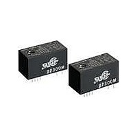
TIMER
Manufacturer
Omron
Type
Solid State Timerr
Datasheet
1.H3FA-B-DC24.pdf
(10 pages)
Specifications of H3FA-AU DC24
Analog / Digital
Analog
Control Method
Dial
Voltage Rating
24 VDC
Mounting
PCB
Display Type
None
Size
36.9 mm x 17.75 mm x 19.5 mm
Features
Timer operation may also be controlled through an external variable resistor
Input Type
Voltage
Output Type
SPST-NO and SPST-NC
Lead Free Status / RoHS Status
Lead free / RoHS Compliant
Lead Free Status / RoHS Status
Lead free / RoHS Compliant


■ Ratings
Note: 1. Permissible ripple: 20% max. (3% max. at 5, 6 V DC-operated models)
■ Characteristics
Note: 1. Add or subtract 10 ms to the ratings when using a timer with a rated time of 1 s.
■ Life-test Curve (Reference Values)
Rated supply voltage
Operating voltage range
Power consumption
Control outputs
Ambient temperature
Ambient humidity
Accuracy of operating time ±0.5% FS max. (See note 1.)
Setting error
Reset time
Influence of voltage
Influence of temperature
Insulation resistance
Dielectric strength
Vibration resistance
Shock resistance
Life expectancy
Approved safety standards UL508, CSA C22.2 No.14
Weight
2. Supply voltage can be selected by short-circuiting (12 V DC) or opening (24 V DC) the specified terminals.
2. Applicable to contact output models.
1,000
700
500
300
100
70
50
30
10
7
5
Where,
Mean
0
250 VAC cosφ=0.4
Item
1
24 VDC L/R=7 ms
5 V DC, 6V DC, 12V DC, 24 V DC (See note 1.)
5 V DC:
6, 12, 24 V DC: 85% to 110% of rated supply voltage
5, 6 V DC:
12 V DC:
24 V DC:
Contact output: SPST-NO + SPST-NC,
3 A at 250 V AC with resistive load,
Minimum applied load: 10 mA at 5 V DC
(Failure level: P, reference value)
Operating:
Storage:
35% to 85%
2
0 to 30 % FS max. (at 20°C , at rated voltage)
10 ms max.
±1% FS max. (2% FS max. for 5, 6, 5/6 V DC-operated models)
±5% FS max. (See note 1.)
100 MΩ min. (at 500 V DC)
1,500 V AC, 50/60 Hz for 1 min (between control output and operating circuit) (See note 2.)
1,000 V AC, 50/60 Hz for 1 min (between contacts not located next to each other) (See note 2.)
Destruction: 10 to 55 Hz with 0.375-mm single amplitude in 3 directions for 1 hour each
Malfunction: 10 to 55 Hz with 0.25-mm single amplitude in 3 directions for 10 minutes each
Destruction: 1,000 m/s
Malfunction: 100 m/s
Mechanical: 10,000,000 operations min. (under no load at 1,800 operations/h)
Electrical:
Contact output models:
Solid-state output models: approx. 10 g
250 VAC cosφ=1
24 VDC cosφ=1
Load current (A)
3
X
100,000 operations min. (3 A at 250 V AC, resistive load at 1,800 operations/h)
X/Mean value × 100 ≤ 20 (%) max.
90% to 110% of rated supply voltage
approx. 230 mW
approx. 270 mW
approx. 330 mW
−10°C to 55°C (with no icing)
−25°C to 65°C (with no icing)
H3FA-AU/ H3FA-BU
4
H3FA-A/ H3FA-B
2
3 times each in 6 directions
2
3 times each in 6 directions
approx. 15 g
5/6 V DC (See note 1.)
12/24 V DC (See notes 1 and 2.)
5/6 V DC:
12/24 V DC:
5/6 V DC:
12 V DC:
24 V DC:
Solid-state output: 150 mA max. at 30 V DC
Residual voltage: 1.0 V max.
H3FA-SAU/ H3FA-SBU
H3FA-SA/ H3FA-SB
90% to 110% of rated supply voltage
85% to 110% of rated supply voltage
approx. 80 mW
approx. 100 mW
approx. 240 mW
H3FA
3
Related parts for H3FA-AU DC24
Image
Part Number
Description
Manufacturer
Datasheet
Request
R

Part Number:
Description:
RELAY TIMER DPST .1SEC-10M 12VDC
Manufacturer:
Omron
Datasheet:
Part Number:
Description:
RELAY TIMER DPST .1SEC-10M 24VDC
Manufacturer:
Omron
Datasheet:
Part Number:
Description:
RELAY TIMER DPST .1SEC-10M 5VDC
Manufacturer:
Omron
Datasheet:
Part Number:
Description:
Timer
Manufacturer:
Omron
Datasheet:

Part Number:
Description:
TIMER
Manufacturer:
Omron
Datasheet:
Part Number:
Description:
TIMER
Manufacturer:
Omron
Datasheet:
Part Number:
Description:
TIMER
Manufacturer:
Omron
Datasheet:

Part Number:
Description:
Solid-state Timer
Manufacturer:
Omron Corporation
Datasheet:
Part Number:
Description:
G6S-2GLow Signal Relay
Manufacturer:
Omron Corporation
Datasheet:
Part Number:
Description:
Compact, Low-cost, SSR Switching 5 to 20 A
Manufacturer:
Omron Corporation
Datasheet:
Part Number:
Description:
Manufacturer:
Omron Corporation
Datasheet:
Part Number:
Description:
Manufacturer:
Omron Corporation
Datasheet: