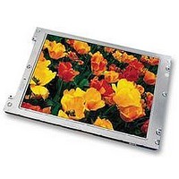
LTA104D183F Toshiba, LTA104D183F Datasheet

LTA104D183F
Specifications of LTA104D183F
Available stocks
Related parts for LTA104D183F
LTA104D183F Summary of contents
Page 1
... Min. Typ. 250 450 --- 100 --- 120 --- 8 ) --- 17 250 320 50,000 =6.0mA(rms), continuous lighting FL (1/12) 26cm COLOR TFT-LCD MODULE (10.4 TYPE) LTA104D183F (p-Si TFT) TENTATIVE RoHS compatible :40kHz ) FL Specifications (H) pixels Max. Unit 4.0 V 2.0 kV(rms) 100 KHz V +0 °C 70 °C ...
Page 2
... Item Operating Starting Force Surface Hardness Min. Typ. V --- 5.0 TP Min. Typ --- Rx 200 --- Ry 100 --- - - Min. Typ. 5 --- 3 (2/12) LTA104D183F Max. Unit Remarks 7.0 V Max. Unit Remarks --- MOhm DC25V Measured at connector 1500 Ohm pin(including conductor 600 Ohm resistance). 1 msec Max. Unit Remarks 2007-10-18 (Ver ...
Page 3
DIMENSIONAL OUTLINE 23.4+/-0.3 9.05 2.05 13.5+/-0.3 9.05 7.1+/-0.3 TENTATIVE 132.6+/-0.3 (88.3) Area) Active 158.4(T/P 172.4(T/P) 161.7+/-0.3 Area) Active 158.4(LCD Opening) 162.4(Bezel 178.45+/-0.3 (3/12) LTD104D183F Unit : mm Standard tolerance : 0.5 1+/-0.15 1+/-0.15 5+/-0.2 0.30+/-0.05 2007-10-18 (Ver.0.1R) ...
Page 4
... DIMENSIONAL OUTLINE TENTATIVE (T/P) (88.3) (117.5) (4/12) LTA104D183F Unit : mm Standard tolerance : 0.5 2007-10-18 (Ver.0.1R) ...
Page 5
... Voltage Generation CN1 Circuit Panel Controller SEQUENCE OF POWER SUPPLIES AND SIGNALS 0. CLK+/- RxIN0+/- RxIN1+/- RxIN2+/- FL Input Voltage 10% 800 x 600 pixels With Touch Panel SFL 10% (5/12) LTA104D183F CCFL Backlight CCFL Backlight LCD Panel X-Driver IC 0.2V 0. SFL FL FL 2007-10-18 (Ver.0.1R) CN3 CN2 CN4 ...
Page 6
... TIMING CHART <H-Sync/V-Sync+DE Mode> Vsync Hsync tvfp tvde DE 600 599 thw Hsync thfp thds RGB Data NCL <DE-Only Mode> (1) Vertical Timing t 3 1line tvw th tvd tvblnk th thde 800 (6/12) LTA104D183F tvde 1 2 2007-10-18 (Ver.0.1R) ...
Page 7
... Symbol Min. t1 608 625 x t3 --- 17.78 t2 600 x t3 600 850 x tc 1024 x tc 26.4 28.44 t4 800 x tc 800 25.0 27.78 (7/12) LTA104D183F typ. Max. unit 625 628 th 17. --- --- th --- --- th --- --- th 600 600 th 1056 tc --- us --- --- tc --- --- ...
Page 8
... Horizontal Reverse(“L” level or Open : Normal, “H” level : Reverse) Non Connection (open) GND Function CCFL Power Supply ( high voltage) Non Connection (open) CCFL Power Supply (low voltage) Function Touch Panel XR Terminal Touch Panel YU Terminal Touch Panel XL Terminal Touch Panel YD Terminal (8/12) LTA104D183F 2007-10-18 (Ver.0.1R) ...
Page 9
... RECOMMENDED TRANSMITTER (DS90C365* by National Semiconductor Corp.) TO LTA104D183F INTERFACE ASSIGNMENT Case1: 6bit Transmitter Input Terminal No. Symbol Terminal Symbol TIN0 44 R0 TIN1 45 R1 TIN2 47 R2 TIN3 48 R3 TIN4 1 R4 TIN5 3 R5 TIN6 4 G0 TIN7 6 G1 TIN8 7 G2 TIN9 9 G3 TIN10 10 G4 TIN11 12 G5 ...
Page 10
... RECOMMENDED TRANSMITTER (DS90C385* by National Semiconductor Corp.) TO LTA104D183F INTERFACE ASSIGNMENT Case2: 8bit Transmitter Input Terminal No. Symbol Terminal Symbol TIN0 51 R0 TIN1 52 R1 TIN2 54 R2 TIN3 55 R3 TIN4 56 R4 TIN6 3 R5 TIN7 4 G0 TIN8 6 G1 TIN9 7 G2 TIN12 11 G3 TIN13 12 G4 TIN14 14 G5 ...
Page 11
... L L Scale of Dark White & ↑ Black ↓ Light White (11/12) LTA104D183F Gray Scale Level --- --- --- --- --- --- --- --- L3… : L60 L61 L62 Red L63 L3… : L60 L61 L62 Green L63 L3… : L60 L61 L62 Blue L63 L3… : L60 L61 L62 White L63 2007-10-18 (Ver.0.1R) ...
Page 12
... Therefore, when designing the whole set, not to be over “the recommended operation conditions”, you should fully take care of supply voltage change, characteristic of connection parts, serge of input-and-output line, and surrounding temperature. 8) DISPOSAL When dispose LCD module, obey to the applicable environmental regulations. (12/12) LTA104D183F 2007-10-18 (Ver.0.1R) ...


