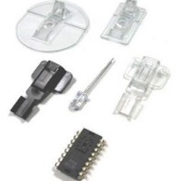
ADNK-7533-TN24 Avago Technologies US Inc., ADNK-7533-TN24 Datasheet - Page 2

ADNK-7533-TN24
Manufacturer Part Number
ADNK-7533-TN24
Description
Reference Design Kit For ADNS-7530
Manufacturer
Avago Technologies US Inc.
Datasheet
1.ADNK-7533-TN24.pdf
(18 pages)
Specifications of ADNK-7533-TN24
Main Purpose
Reference Design, Optical Mouse
Utilized Ic / Part
ADNS-7530
Lead Free Status / RoHS Status
Lead free / RoHS Compliant
Secondary Attributes
-
Embedded
-
Primary Attributes
-
Lead Free Status / Rohs Status
Details
Optical Mouse Basics
The image-based optical mouse sensor takes snap shots
of the surface it is navigating on. It measures changes in
position by comparing the sequential images (frames) and
mathematically determines the direction and magnitude
of movement. The traditional duel-channel optical encoder
generates the quadrature Z-wheel movement signals. This
design guide illustrates the hardware connection of a laser
mouse with standard configuration; as well as the firmware
management and the handling of the USB protocols. USB
protocol provides a standard way of reporting mouse
movement and button presses to the PC. The Windows
HID driver interprets the USB data and performs the cursor
movements and mouse clicks.
The functional block diagram of the reference design
mouse is shown in Figure 1. The optical sensor detects the
X and Y movements. A mechanical quadrature encoder
provides the Z-wheel movement. Each of the button
switches is pulled up normally and provides a Ground
when pressed. The TSP61070 boost regulator maintains
the 2.7 V operating voltage for the reference design mouse
from two regular AAA Alkaline batteries in serial. The
controls and data are transmitted through 2.4GHz RF by
nRF24L01 transceiver and received by the nRF2401A trans-
ceiver at the dongle. The control of the mouse is managed
by the MSP430F1222 microcontroller; while the dongle is
controlled by Silicon Laboratories C8051F326 USB control-
ler.
Figure 1. ADNK-7533-TN24 Reference Design Mouse Functional Block Diagram
2
Right Button
ADNS-7530
Left Button
Z-Encoder
Sensor
Mouse
Wheel
Button
Avago
Laser
Quadrature Signals
MOTION
SCLK
MISO
MOSI
NCS
Texas Instrument
MSP430F1222
Microcontroller
Mouse
Control and Data
Instrument
TPS61070
Regulator
Texas
Boost
Transceiver
nRF24L01
Nordic
Mechanical Z-Wheel
The motion of Z-wheel is detected using the traditional
method by decoding the quadrature signal generated by
mechanical encoder. The Z-pinwheel is connected to the
Z-encoder through its shaft. The rotational movement of
the shaft is decoded into on and off levels in a quadrature
output pattern. Every change in the Z-encoder outputs
represents a count of mouse movement. Comparing the
last state of the Z-encoder to the current state derives
direction information. As shown in Figure 2, traveling
in clockwise direction produces a unique set of state
transitions, and traveling in counter clockwise direction
produces another set of unique state transitions. In
this reference design, only the motion at the Z-wheel is
detected using this method.
Mouse Buttons
Mouse buttons are connected as standard switches. These
switches are pulled up by the pull up resistors inside the
microcontroller. When the user presses a button, the switch
will be closed and the pin will be pulled LOW to GND. A LOW
state at the pin is interpreted as the button being pressed. A
HIGH state is interpreted as the button has been released or
the button is not being pressed. Normally the switches are
debounced in firmware for 15-20ms. In this reference design
there are three switches: left, Z-wheel, and right.
Transceiver
nRF2401A
Nordic
Control and Data
Dongle
Microcontroller
C8051F326
Silab
USB


