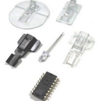
ADNK-7533-TN24 Avago Technologies US Inc., ADNK-7533-TN24 Datasheet - Page 4

ADNK-7533-TN24
Manufacturer Part Number
ADNK-7533-TN24
Description
Reference Design Kit For ADNS-7530
Manufacturer
Avago Technologies US Inc.
Datasheet
1.ADNK-7533-TN24.pdf
(18 pages)
Specifications of ADNK-7533-TN24
Main Purpose
Reference Design, Optical Mouse
Utilized Ic / Part
ADNS-7530
Lead Free Status / RoHS Status
Lead free / RoHS Compliant
Secondary Attributes
-
Embedded
-
Primary Attributes
-
Lead Free Status / Rohs Status
Details
Texas Instrument MSP430F1222 Microcontroller
The Texas Instruments MSP430 family of ultra-low power
microcontrollers consists of several devices featuring
different sets of peripherals targeted for various applica-
tions. The architecture, combined with five low-power
modes, is optimized to achieve extended battery life in
portable measurement applications. The device features
a powerful 16-bit RISC CPU, 16-bit registers, and constant
generators that attribute to maximum code efficiency.
The Digitally Controlled Oscillator (DCO) allows wake-
up from low-power modes to active mode in less than 6
µsec.
The specific device used in this reference design is the
MSP430F1222 with 28 pin to accommodate ample
amount of I/O. It is an ultra-low power mixed-signal mi-
crocontrollers with a built-in 16-bit timer, 10-bit A/D
converter with integrated reference and Data Transfer
Controller (DTC), and 14 (20 pin package) or 22 (28 pin
package) general purpose I/O pins. The MSP430x12x2
series microcontrollers have built-in communication ca-
pability using asynchronous (UART) and synchronous
(SPI) protocols. The architecture, combined with five low
power modes is optimized to achieve extended battery
life on wireless application.
4
Features
•
•
•
•
•
•
•
•
•
•
•
•
•
•
•
•
For Complete Module Descriptions, See the TI
MSP430x1xx Family User’s Guide, Literature Number
SLAU049
Low Supply Voltage Range 1.8 V to 3.6 V
Ultralow-Power Consumption:
-
-
-
Five Power Saving Modes
Wake-Up From Standby Mode in less than 6 µs
16-Bit RISC Architecture, 125 ns Instruction Cycle
Time
Basic Clock Module Configurations:
-
-
-
-
-
-
16-Bit Timer_A With Three Capture/Compare
Registers
10-Bit, 200-ksps A/D Converter With Internal
Reference, Sample-and-Hold, Autoscan, and Data
Transfer Controller
Serial Communication Interface (USART0) With
Software-Selectable Asynchronous UART or
Synchronous SPI Serial Onboard Programming, No
External Programming Voltage Needed Programmable
Code Protection by Security Fuse
Supply Voltage Brownout Protection
4KB + 256B Flash Memory 256B RAM
Available in 28-Pin Plastic SOWB, 28-Pin Plastic TSSOP,
and 32-Pin QFN Packages
Active Mode: 200 µA at 1 MHz, 2.2 V
Standby Mode: 0.7 µA
Off Mode (RAM Retention): 0.1 µA
Various Internal Resistors
Single External Resistor
32-kHz Crystal
High Frequency Crystal
Resonator
External Clock Source


