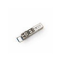
AFCT-5705LZ Avago Technologies US Inc., AFCT-5705LZ Datasheet - Page 9

AFCT-5705LZ
Manufacturer Part Number
AFCT-5705LZ
Description
LX SFP Std Delatch RoHS
Manufacturer
Avago Technologies US Inc.
Series
-r
Datasheet
1.AFCT-5705LZ.pdf
(20 pages)
Specifications of AFCT-5705LZ
Mounting Type
SFP
Voltage - Supply
3.14 V ~ 3.47 V
Connector Type
LC Duplex
Applications
Ethernet
Wavelength
1310nm
Data Rate
1.25Gbd
Product
Transceiver
Maximum Rise Time
400 ps, 260 ps
Maximum Fall Time
400 ps, 260 ps
Pulse Width Distortion
0.227 ns, 0.267 ns
Operating Supply Voltage
3.14 V to 3.47 V
Maximum Operating Temperature
+ 85 C
Minimum Operating Temperature
- 10 C
Package / Case
SFP-20
Function
SFP Optical Transceivers with Optional DMI for Gigabit Ethernet
Lead Free Status / RoHS Status
Lead free / RoHS Compliant
For Use With
Singlemode Glass
Lead Free Status / RoHS Status
Lead free / RoHS Compliant
Notes:
1
2. Over temperature and Beginning of Life.
3. MSA filter is required on host board 10 Hz to 1 MHz. See Figure 3
4. LVTTL, External 4.7 - 10 K: Pull-Up Resistor required
5. LVTTL, Internal 4.7 - 10 K: Pull-Up Resistor required for TX_Disable
6. Internally ac coupled and terminated (100 Ohm differential)
7. Internally ac coupled and load termination located at the user SerDes
8. Contributed DJ is measured on an oscilloscope in average mode with 50% threshold and K28.5 pattern
9. Contributed total jitter is calculated from DJ and RJ measurements using TJ = RJ + DJ. Contributed RJ is calculated for 1x10-12 BER by multiply-
10. Per IEEE 802.3
Table 6. Transmitter Optical Characteristics
Notes:
1. Class 1 Laser Safety per FDA/CDRH
2. In conformance with FC-PI Figure 18, which defines allowable trade-off between wavelength, spectral width and OMA.
3. Contributed DJ is measured on an oscilloscope in average mode with 50% threshold and K28.5 pattern.
4. Contributed total jitter is calculated from DJ and RJ measurements using TJ = RJ + DJ. Contributed RJ is calculated for 1x10-12 BER by multiply-
5. IEEE 802.3
6. Eye shall be measured with respect to the mask of the eye using filter defined in IEEE 802.3 section 38.6.5
9
Parameter
Modulated Optical Output Power (OMA)
(Peak-to-Peak) 1.0625 Gb/s
Average Optical Output Power
Optical Extinction Ratio
TX Optical Eye Mask Margin 1.25 Gb/s
Center Wavelength
Spectral Width - rms
Optical Rise/Fall Time
Relative Intensity Noise
Contributed Deterministic Jitter (Transmitter)
1.0625 Gb/s
Contributed Total Jitter (Transmitter)
1.0625 Gb/s
Contributed Total Jitter (Transmitter)
1.25 Gb/s
POUT TX_DISABLE Asserted
ing the RMS jitter (measured on a single rise or fall edge) from the oscilloscope by 14. Per FC-PI (Table 9 - SM jitter output, note 1), the actual
contributed RJ is allowed to increase above its limit if the actual contributed DJ decreases below its limits, as long as the component output DJ
and TJ remain within their specified FC-PI maximum limits with the worst case specified component jitter input.
The module supply voltages, V
cc
T and V
cc
R, must not differ by more than 0.5V or damage to the device may occur.
Symbol
OMA
ER
MM
tr, tf
RIN
DJ
TJ
TJ
POFF
POUT
λC
σ, rms
Minimum
174
-7.6
9
0
1270
-9.5
Typical
30
Maximum
-3
1355
2.1
260
-120
0.09
85
0.27
251
0.284
227
-45
Unit
μW OMA
dBm OMA
dBm
dB
%
nm
nm
ps
dB/Hz
UI
ps
UI
ps
UI
ps
dBm
Notes
Note 2
Note 1
Notes 5, 6
Note 2
Note 2
20-80%
Note 3
Note 4
Note 5


