HFBR-0539Z Avago Technologies US Inc., HFBR-0539Z Datasheet
HFBR-0539Z
Manufacturer Part Number
HFBR-0539Z
Description
DC-12MBd Profibus 650nm Eval Kit
Manufacturer
Avago Technologies US Inc.
Specifications of HFBR-0539Z
Main Purpose
Interface, Fiber Optics
Embedded
No
Utilized Ic / Part
HFBR-1515BZ, HFBR-2515BZ
Primary Attributes
DC ~ 12MBd TTL
Secondary Attributes
SMA Connectors
Operating Voltage
5 V
Description/function
Versatile Fiber Optic Evaluation Kit
Maximum Operating Temperature
+ 85 C
Minimum Operating Temperature
- 40 C
Operating Current
6.2 mA
Leaded Process Compatible
Yes
Rohs Compliant
Yes
Peak Reflow Compatible (260 C)
Yes
Lead Free Status / RoHS Status
Lead free / RoHS Compliant
For Use With/related Products
HFBR-1515BZ, HFBR-2515BZ
Lead Free Status / RoHS Status
Lead free / RoHS Compliant
Other names
516-2252


HFBR-0539Z Evaluation Kit
DC to 12 MBd Profibus 650 nm Fiber Optics Eval Kit
User Guide
Introduction
HFBR-0539Z evaluation kit is used to evaluate Avago fiber optic device HFBR-1515BZ and HFBR-2515BZ. The evaluation
kit is equipped with necessary documents and accessories to ease product evaluation and verification.
Evaluation Kit
HFBR-0539Z contains:
1. Evaluation board
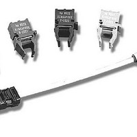
2. HFBR-1515BZ and HFBR-2515BZ unit
3. HCS® Cable with ST connector
4. HFBR-1515BZ /2515BZ datasheet
5. User guide document
Evaluation Board
The basic evaluation board that you receive from Avago incorporates transmitter driver IC SN75451BD, some passive
components, and SMA connectors for the TX input (TXD) and RX output (RXD) port connection. This basic evaluation
board allows you to connect waveform/pattern generator to the TXD with TTL input signal. Receiver’s output signal can
be monitored from the RXD or RXout with oscilloscope by using high impedance setting.
Initial Setup
1. Connect 5 V supply voltage to TXVCC and RXVCC
2. Connect 0 V to TXGND and RXGND
3. Connect TXD to pattern generator output
4. Connect RXout to Oscilloscope with high impedance probe
Bit Error Rate Test Setup
Though the transmitter driver IC’s input and receiver’s output is based on TTL logic (high impedance), the board can be
modified to connect 50 ohm load instrument by doing the following steps:
1. Put R2 (50 ohm resistor).
2. Remove R3 (0 ohm resistor).
3. Put R4 (0 ohm resistor) and R7 (50 ohm resistor).
4. Put U3 (SN74LVC2G125).
5. Connect BVCC (5 V) and BGND (0 V).
HCS® is a trademark of OFS
Related parts for HFBR-0539Z
Image
Part Number
Description
Manufacturer
Datasheet
Request
R

Part Number:
Description:
Fiber Optic Transmitters, Receivers, Transceivers 1300nm 155MBd 16-pin DIP ST Rx
Manufacturer:
Avago Technologies US Inc.

Part Number:
Description:
FIBER OPTIC TX 125 MBD 650N
Manufacturer:
Avago Technologies US Inc.
Datasheet:

Part Number:
Description:
Fiber Optic Evaluation Kit
Manufacturer:
Avago Technologies US Inc.
Datasheet:

Part Number:
Description:
RECEIVER FIBER OPTIC ST 266MBD
Manufacturer:
Avago Technologies US Inc.
Datasheet:

Part Number:
Description:
RCVR OPT HI SPEED VERS LINK HORZ
Manufacturer:
Avago Technologies US Inc.
Datasheet:

Part Number:
Description:
RCVR OPT HI SPEED VERS LINK VERT
Manufacturer:
Avago Technologies US Inc.
Datasheet:

Part Number:
Description:
TXRX OPTICAL 850NM VCSEL MT-RJ
Manufacturer:
Avago Technologies US Inc.
Datasheet:

Part Number:
Description:
TXRX MM SFP LC CONN BAIL DELATCH
Manufacturer:
Avago Technologies US Inc.
Datasheet:

Part Number:
Description:
TXRX MMF SFP GBE/FC BAIL DELATCH
Manufacturer:
Avago Technologies US Inc.
Datasheet:

Part Number:
Description:
XMITTER FIBER OPTIC 266MBD ST
Manufacturer:
Avago Technologies US Inc.
Datasheet:

Part Number:
Description:
OPTOCOUPLER GATE DRV 2A 16-SOIC
Manufacturer:
Avago Technologies US Inc.
Datasheet:
Part Number:
Description:
OPTOCOUPLER 2CH 2.5A 16-SOIC
Manufacturer:
Avago Technologies US Inc.
Datasheet:

Part Number:
Description:
OPTOCOUPLER GATE DRV 0.4A 16SOIC
Manufacturer:
Avago Technologies US Inc.
Datasheet:

Part Number:
Description:
OPTOCOUPLER 2.0A 250KHZ 8-DIP
Manufacturer:
Avago Technologies US Inc.
Datasheet:

Part Number:
Description:
OPTOCOUPLER 2.0A 250KHZ GW 8-SMD
Manufacturer:
Avago Technologies US Inc.
Datasheet:
HFBR-0539Z Summary of contents
Page 1
... HFBR-0539Z Evaluation Kit MBd Profibus 650 nm Fiber Optics Eval Kit User Guide Introduction HFBR-0539Z evaluation kit is used to evaluate Avago fiber optic device HFBR-1515BZ and HFBR-2515BZ. The evaluation kit is equipped with necessary documents and accessories to ease product evaluation and verification. Evaluation Kit HFBR-0539Z contains: 1 ...
Page 2
For product information and a complete list of distributors, please go to our web site: Avago, Avago Technologies, and the A logo are trademarks of Avago Technologies in the United States and other countries. ...