4-141 Cinch Connectors, 4-141 Datasheet - Page 198
4-141
Manufacturer Part Number
4-141
Description
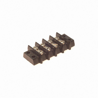
BARRIER BLOCK 4POS .438"
Manufacturer
Cinch Connectors
Series
141r
Type
Wire to Boardr
Specifications of 4-141
Terminal Block Type
Barrier Block
Number Of Circuits
4
Number Of Positions
8
Pitch
0.438" (11.12mm)
Number Of Rows
2
Current
20A
Voltage
250V
Wire Gauge
14 AWG
Mounting Type
Chassis Mount or Panel Mount
Top Termination
Screws
Bottom Termination
Closed
Barrier Type
2 Wall (Dual)
Features
Flange
Color
Black
Operating Temperature
-55°F ~ 300°F
Material - Insulation
Phenol Formaldehyde (Phenolic)
Material Flammability Rating
UL94 V-1
Product
Barrier Terminal Blocks
Number Of Positions / Contacts
4
Current Rating
20 A
Voltage Rating
250 V
Wire Gauge Max (awg)
14
Current, Rating
20 A (Max.)
Length
2.500 in.
Material, Block
Brass
Material, Screw
Steel
Mounting Style
Bottom
Plating, Screw
Nickel over Copper Flash
Screw Size
6-32 x 1⁄4
Temperature Range
-55 to +300 °F
Lead Free Status / RoHS Status
Lead free / RoHS Compliant
Lead Free Status / RoHS Status
Lead free / RoHS Compliant, Lead free / RoHS Compliant
Other names
4-141-P
4141-P
CBB204
4141-P
CBB204
Available stocks
Company
Part Number
Manufacturer
Quantity
Price
Company:

Part Number:
4-1415053-1
Manufacturer:
TE
Quantity:
5 000
Company:
Part Number:
4-1415053-1
Manufacturer:
TE
Quantity:
20 000
Company:
Part Number:
4-1415053-1
Manufacturer:
TE
Quantity:
35 000
Company:
Part Number:
4-1415535-1
Manufacturer:
TE
Quantity:
5 000
Company:
Part Number:
4-1415535-1
Manufacturer:
TE
Quantity:
20 000
Part Number:
4-1419123-9
Manufacturer:
TE/泰科
Quantity:
20 000
Part Number:
4-1419128-4
Manufacturer:
TE/泰科
Quantity:
20 000


Ordering Information
Dura-Con
High Reliability
All-Plastic
Contact Arrangements
(Face view of pin insulator)
(Use reverse order for socket)
** - See p. 5-12 for std. hardware dims. See p. 5-13 for non-std. hardware & p. 5-31 for Mil spec. hardware both sold separately.
***- Length Tolerance: solid wire = ± 3/32”, standard wire = ± 1/4”.
* - Indicates Cinch std. option.
Cinch Dura-Con D Connector
Insulator Type
*D = Thermoplastic
Glass Reinforced
Mounting Type
*A = Screw Mount Flange
No. of Contacts
9, 15, 21, 25, 31, 37, 51
Contact Type
P – Pin (Plug)
S – Socket (Receptacle)
Wire Size in AWG
5 = 25 AWG Solid Copper
6 = 26 AWG Stranded
S = Solder Cup (Skip to Mounting Hardware)
Wire Type
E = MIL-W-16878/4, 7 Strand
C = Solid Copper - Uninsulated
(
Consult factory for non-standard wire types)
DC D A 37 P 6 E 2 -18.0 K
.050" (1.27mm) Density
Solder Cup/Wire
D-Microminiature
5-5
Call Toll Free: 1 (800) 323-9612
Mounting Hardware**
B = No Hardware
F = Float Mount
R = Reverse Float Mount
K = Jackscrew (Standard)
L = Jackscrew (Low Profile)
P = Jackpost, MIL-C-83513/5-07
Lead Length in inches***
00.5 Solid copper wire only
01.0 Solid copper wire only
02.0 Solid copper wire only
18.0 Stranded wire only
24.0 Stranded wire only
36.0 Stranded wire only
48.0 Stranded wire only
Insulation
Color or Wire Finish
*2 = Yellow (Stranded Wire)
*4 = Gold-Plated (Solid Wire Only)
*5 = Color Coded Per MIL-Std. (681)
System 1. (Stranded Wire Only)
1 = White
3 = Tin-Plated
Related parts for 4-141
Image
Part Number
Description
Manufacturer
Datasheet
Request
R

Part Number:
Description:
BARRIER BLOCK 4POS .375"
Manufacturer:
Cinch Connectors
Datasheet:

Part Number:
Description:
BARRIER BLOCK 4POS .563"
Manufacturer:
Cinch Connectors
Datasheet:

Part Number:
Description:
CONN BARRIER BLOCK .375" 4 POS
Manufacturer:
Cinch Connectors
Datasheet:

Part Number:
Description:
D-Subminiature Connectors THUMBSCREW
Manufacturer:
Cinch Connectors
Datasheet:
