09 12 003 3101 HARTING, 09 12 003 3101 Datasheet - Page 14
09 12 003 3101
Manufacturer Part Number
09 12 003 3101
Description
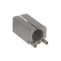
Sealed Ethernet Connector
Manufacturer
HARTING
Datasheet
1.09_99_000_0099.pdf
(25 pages)
Specifications of 09 12 003 3101
Connector Type
Sealed Ethernet
Lan Category
Cat5
No. Of Ports
1
Leaded Process Compatible
Yes
Gender
Receptacle
Performance Category
Cat 5e
Usoc Codes
RJ45
Shielding
Unshielded
Housing Material
Plastic
Lead Free Status / RoHS Status
Lead free / RoHS Compliant


Terminations
Axial screw terminal
This termination combines the benefits of screw and crimp termi-
nations:
● Less space required
● Easy handling
● No special tools
Remarks on the axial screw technique
The wire gauges mentioned in the catalogue refer to geometric
wire gauges of cables.
Background:
According to DIN VDE 0295 for cables and insulated wires the
wire gauge will be determined by conductance (Ω/km) and maxi-
mum wire diameter. A minimum cable diameter is not specified!
(Example:nominal wire gauge 95 mm² → real, geometric wire
gauge 89 mm²)
Recommendation:
The use of cables with an extreme geometric wire gauge deviati-
on should be checked separately with the use of the axial screw
termination.
Wire assembly according to VDE 0295
Wire gauge
(mm²)
0.14
0.25
0.34
0.38
0.75
120
150
185
240
0.5
1.5
2.5
10
16
25
35
50
70
95
1
4
6
Stranded wires VDE
0295 class 2
19 x 1.83
19 x 2.17
19 x 2.52
37 x 2.03
37 x 2.27
37 x 2.52
61 x 2.24
7 x 0.30
7 x 0.37
7 x 0.43
7 x 0.52
7 x 0.67
7 x 0.85
7 x 1.05
7 x 1.35
7 x 1.70
7 x 2.13
7 x 2.52
Fine stranded wires
VDE 0295 class 5
1225 x 0.50
128 x 0.40
200 x 0.40
280 x 0.40
400 x 0.40
356 x 0.50
485 x 0.50
614 x 0.50
765 x 0.50
944 x 0.50
14 x 0.15
19 x 0.15
12 x 0.20
16 x 0.20
24 x 0.20
32 x 0.20
30 x 0.25
50 x 0.25
56 x 0.30
84 x 0.30
80 x 0.40
1120 x 0.20
1340 x 0.30
1690 x 0.30
2123 x 0.30
1470 x 0.40
1905 x 0.40
140 x 0.15
224 x 0.15
192 x 0.20
320 x 0.20
512 x 0.20
800 x 0.20
705 x 0.30
990 x 0.30
18 x 0.10
32 x 0.10
42 x 0.10
21 x 0.15
28 x 0.15
42 x 0.15
56 x 0.15
84 x 0.15
Strain relief:
For safe operation the cable must be fixed at an adequate
distance from the terminal to ensure that the contact is protected
against radial stress.
Details for professional strain relief design can be found in the
standard DIN VDE 0100-520: 2003-06 (see enclosed table).
Cables:
The axial screw technology is developed for wires according to
VDE 0295 class 5 (see table: Wire assembly according to VDE
0295). Deviating cable assemblies have to be tested separately.
Assembly remarks:
Before starting the assembly the user must ensure that the axial
cone is screwed fully downward to completely open the contact
chamber.
After stripping the cable insulation the strands must not be
twisted and the maximum cable insulation must not exceed the
recommended dimension.
Insert the wire completely into the contact chamber until the
copper strands reach the bottom. Keep the cable in position
while applying the recommended tightening torque.
Maintenance of the axial screw termination:
After initial assembly it is only allowed to reapply the recommen-
ded tightening torque once in order to avoid damage to individual
cable strands.
Outer cable diameter
Super fine stranded wires VDE 0295 class 6
15 < D < 20
20 < D < 40
9 < D < 15
D ≤ 9
(mm)
1280 x 0.10
2048 x 0.10
3200 x 0.10
128 x 0.10
192 x 0.10
320 x 0.10
512 x 0.10
768 x 0.10
18 x 0.10
32 x 0.10
42 x 0.10
18 x 0.10
64 x 0.10
96 x 0.10
Maximum fixing distance
horizontal
250
300
350
400
1040 x 0.07
1560 x 0.07
2600 x 0.07
100 x 0.07
131 x 0.07
195 x 0.07
260 x 0.07
392 x 0.07
651 x 0.07
36 x 0.07
65 x 0.07
88 x 0.07
(mm)
vertical
400
400
450
550
1280 x 0.05
128 x 0.05
174 x 0.05
194 x 0.05
256 x 0.05
384 x 0.05
512 x 0.05
768 x 0.05
72 x 0.05
00 .
15
Han
Related parts for 09 12 003 3101
Image
Part Number
Description
Manufacturer
Datasheet
Request
R

Part Number:
Description:
Cable Gland (Clamp)
Manufacturer:
HARTING
Datasheet:

Part Number:
Description:
RJ45 ETHERNET CONNECTOR, JACK 5WAY PANEL
Manufacturer:
HARTING
Datasheet:

Part Number:
Description:
RJ45 ETHERNET CONNECTOR, PLUG 8WAY CABLE
Manufacturer:
HARTING
Datasheet:
Part Number:
Description:
Han Brid-RJ45C-female Insulation Body
Manufacturer:
HARTING

Part Number:
Description:
CONN HOUSING 6POS .156 W/O RAMP
Manufacturer:
Molex Inc
Datasheet:

Part Number:
Description:
CONN HOUSING 3POS .156 W/RAMP
Manufacturer:
Molex Inc
Datasheet:

Part Number:
Description:
CONN HOUSING 3POS .156 W/POLAR
Manufacturer:
Molex Inc
Datasheet:

Part Number:
Description:
CONN HOUSING 5POS .156 W/RAMP
Manufacturer:
Molex Inc
Datasheet:

Part Number:
Description:
CONN HOUSING 5POS .156 W/POLAR
Manufacturer:
Molex Inc
Datasheet:

Part Number:
Description:
CONN HOUSING 6POS .156 W/RAMP
Manufacturer:
Molex Inc
Datasheet:

Part Number:
Description:
CONN HOUSING 6POS .156 W/RAMP
Manufacturer:
Molex Inc
Datasheet:

Part Number:
Description:
CONN HOUSING 6POS .156 W/POLAR
Manufacturer:
Molex Inc
Datasheet:

Part Number:
Description:
CONN HOUSING 8POS .156 W/RAMP
Manufacturer:
Molex Inc
Datasheet:

Part Number:
Description:
CONN HOUSING 9POS .156 W/RAMP
Manufacturer:
Molex Inc
Datasheet: