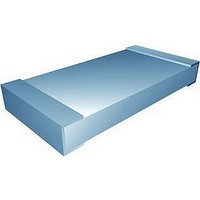
CHP1206L13M7GNT Vishay, CHP1206L13M7GNT Datasheet - Page 5

CHP1206L13M7GNT
Manufacturer Part Number
CHP1206L13M7GNT
Description
RESISTOR, THICK FILM, 13.7MOHM, 250mW, 2%
Manufacturer
Vishay
Series
CHPr
Datasheet
1.CHP1206L10M2GNT.pdf
(9 pages)
Specifications of CHP1206L13M7GNT
Resistance
13.7Mohm
Resistance Tolerance
± 2%
Power Rating
250mW
Voltage Rating
150V
Resistor Element Material
Thick Film
Temperature Coefficient
± 200ppm/°C
Lead Free Status / RoHS Status
Lead free / RoHS Compliant
www.vishay.com
58
CHP, HCHP
Vishay Sfernice
SUGGESTED LAND PATTERN (Option 0063)
Option: High Temperature (please consult)
For applications such as down hole drilling, high temperature withstanding is required. Vishay Sfernice offers an option
for utilization on extended temperature range: [- 55 °C; + 215 °C] powered (and up to 230 °C unpowered).
For guidance in designs, please refer to application note: 53047 Power Dissipation Considerations in High Precision Vishay
Sfernice Thin Film Chip Resistors and Arrays (P, PRA etc.) (High Temperature Application) www.vishay.com/doc?53047.
Option to order 0151:
Please consult Vishay Sfernice
Parts have double and organic coating above mineral coating (overglaze)
External coating color: Blue
Marking: HT
Terminations: Gold (< 1 µm) for reflow or conductive glue
Option: Marking
Option to order 0013:
Marking of ohmic value and tolerance:
Sizes: 0805 to 1005: 3 digits marking (according to EIA-96)
Sizes: 1206 to 2010: 4 digits marking (same codification than in the ordering procedure)
Tolerance indicated by a color dot.
Option to order 0014:
Marking of ohmic value:
Sizes 0805 to 1005: 3 digits marking (according to EIA-96)
Sizes 1206 to 2010: 4 digits marking (same codification than in the ordering procedure)
No standard marking available for smaller sizes.
A price adder will apply to the unit price of the parts for options 0013 and 0014.
CHIP SIZE
1206
1505
1020
2010
2512
PERFORMANCE
TESTS
Termination adhesion
Resistance to solder heat
Rapid temperature change
Climatic sequence
Humidity (steady state)
Moisture resistance
Short time overload
Load life
Phase A dry heat
Phase B damp heat
Phase C cold - 55 °C
Phase D damp heat 5 cycles
- 55 °C
(< 0.25 % at Pn at 70 °C during 1000 h)
85 °C/85 % RH/Pn/10
1000 h at rated power
90’/30’ at + 70 °C
Immersion 10 s
in Sn/Pb 60/40
For technical questions, contact:
CONDITIONS
3.91 (0.154)
4.66 (0.183)
3.39 (0.133)
5.93 (0.233)
7.20 (0.283)
at + 260 °C
5N for 10 s
AEC-Q200
5 cycles
56 days
6.25 Pn
1000 h
High Stability Resistor Chips
for 2 s
Z
max.
Thick Film Technology
+ 155 °C
Z
max.
G
min.
DIMENSIONS (in millimeters)
± (0.25 % + 0.05 Ω)
± (0.25 % + 0.05 Ω)
± (0.25 % + 0.05 Ω)
± (0.25 % + 0.05 Ω)
REQUIREMENTS
± (1 % + 0.05 Ω)
± (1 % + 0.05 Ω)
± (1 % + 0.05 Ω)
0.5 % + 0.05 Ω
sfer@vishay.com
1000 h
0.50 (0.020)
0.50 (0.020)
0.50 (0.020)
0.50 (0.020)
0.50 (0.020)
G
min.
< 0.25 %
1000 h
X
max.
Max. < 3 % + 0.05 Ω
TYPICAL VALUES
AND DRIFTS
< ± 0.1 %
< ± 0.1 %
< ± 0.1 %
< ± 0.2 %
< ± 0.2 %
< ± 0.1 %
Document Number: 52023
< 0.5 %
2000 h
1.73 (0.068)
1.45 (0.057)
5.21 (0.205)
2.67 (0.105)
3.19 (0.126)
X
Revision: 15-Sep-10
max.
10 000 h
< 1 %


