MAX16804ATP+ Maxim Integrated Products, MAX16804ATP+ Datasheet - Page 6
MAX16804ATP+
Manufacturer Part Number
MAX16804ATP+
Description
LED Drivers IC LED DRIVER HIGH BRIGHT
Manufacturer
Maxim Integrated Products
Datasheet
1.MAX16804ATPT.pdf
(10 pages)
Specifications of MAX16804ATP+
Low Level Output Current
35 mA
High Level Output Current
350 mA
Operating Supply Voltage
5.5 V to 40 V
Maximum Power Dissipation
2758.6 mW
Maximum Operating Temperature
+ 125 C
Mounting Style
SMD/SMT
Package / Case
TQFN-20
Minimum Operating Temperature
- 40 C
Lead Free Status / RoHS Status
Lead free / RoHS Compliant


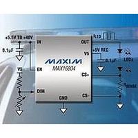
High-Voltage, 350mA LED Driver with
Analog and PWM Dimming Control
The MAX16804 is a high-current regulator capable of
providing up to 350mA of current to one or more strings
of HB LEDs. A wide operating input voltage range of
5.5V to 40V makes the MAX16804 ideal for automotive
applications. A +5V regulated output provides up to
2mA of current to power external circuitry. In addition,
the MAX16804 features thermal and output short-circuit
protection. The wide operating voltage range helps
protect the MAX16804 against large transients such as
those found in load-dump situations up to 45V.
The MAX16804 uses a feedback loop to control the out-
put current. The differential voltage across the sense
resistor is compared to a fixed reference voltage, and the
error is amplified to serve as the drive to the internal pass
device (see the Functional Diagram ). The regulation
point is factory-set at (V
regulated current is user-defined by the value of R
6
_______________________________________________________________________________________
GND
DIM
EN
Detailed Description
MAX16804
200Hz RAMP
CS+
GENERATOR
TRIMMED
BANDGAP
- V
CS-
) = 198 ±6mV. The
1.25V
DETECTOR
210mV
PULSE
IN
SHUTDOWN
THERMAL
SENSE
REGULATOR
.
The MAX16804 is a current controller internally opti-
mized for driving the impedance range expected from
one to ten or more HB LEDs.
The MAX16804’s dimming input functions with either an
analog or PWM control signal. If the pulse detector
detects three edges of a PWM signal with a frequency
range between 80Hz to 2kHz, the MAX16804 synchro-
nizes to external PWM input signal and pulse-width-
modulates the LED current. If an analog control signal
is applied to DIM, the MAX16804 compares the DC
input to an internally generated 200Hz ramp to pulse-
width-modulate the LED current.
The output current duty cycle is adjustable from 0% to
100% (0.21V < V
Use the following formula to calculate the output cur-
rent duty cycle:
V5
Duty cycle = (V
MUX
I_
REG
POR
DIM
< 3.1V).
DIM
Functional Diagram
- 0.21V) / (2.895V)
DIFFERENTIAL
AMPLIFIER
Dimming Input (DIM)
SENSE
IN
CS+
CS-
OUT
(1)
Related parts for MAX16804ATP+
Image
Part Number
Description
Manufacturer
Datasheet
Request
R


Part Number:
Description:
MAX7528KCWPMaxim Integrated Products [CMOS Dual 8-Bit Buffered Multiplying DACs]
Manufacturer:
Maxim Integrated Products
Datasheet:
Part Number:
Description:
Single +5V, fully integrated, 1.25Gbps laser diode driver.
Manufacturer:
Maxim Integrated Products
Datasheet:
Part Number:
Description:
Single +5V, fully integrated, 155Mbps laser diode driver.
Manufacturer:
Maxim Integrated Products
Datasheet:
Part Number:
Description:
VRD11/VRD10, K8 Rev F 2/3/4-Phase PWM Controllers with Integrated Dual MOSFET Drivers
Manufacturer:
Maxim Integrated Products
Datasheet:
Part Number:
Description:
Highly Integrated Level 2 SMBus Battery Chargers
Manufacturer:
Maxim Integrated Products
Datasheet:
Part Number:
Description:
Current Monitor and Accumulator with Integrated Sense Resistor; ; Temperature Range: -40°C to +85°C
Manufacturer:
Maxim Integrated Products
Part Number:
Description:
TSSOP 14/A�/RS-485 Transceivers with Integrated 100O/120O Termination Resis
Manufacturer:
Maxim Integrated Products
Part Number:
Description:
TSSOP 14/A�/RS-485 Transceivers with Integrated 100O/120O Termination Resis
Manufacturer:
Maxim Integrated Products
Part Number:
Description:
QFN 16/A�/AC-DC and DC-DC Peak-Current-Mode Converters with Integrated Step
Manufacturer:
Maxim Integrated Products
Part Number:
Description:
TDFN/A/65V, 1A, 600KHZ, SYNCHRONOUS STEP-DOWN REGULATOR WITH INTEGRATED SWI
Manufacturer:
Maxim Integrated Products
Part Number:
Description:
Integrated Temperature Controller f
Manufacturer:
Maxim Integrated Products
Part Number:
Description:
SOT23-6/I�/45MHz to 650MHz, Integrated IF VCOs with Differential Output
Manufacturer:
Maxim Integrated Products
Part Number:
Description:
SOT23-6/I�/45MHz to 650MHz, Integrated IF VCOs with Differential Output
Manufacturer:
Maxim Integrated Products
Part Number:
Description:
EVALUATION KIT/2.4GHZ TO 2.5GHZ 802.11G/B RF TRANSCEIVER WITH INTEGRATED PA
Manufacturer:
Maxim Integrated Products