MAX16804ATP+ Maxim Integrated Products, MAX16804ATP+ Datasheet - Page 7
MAX16804ATP+
Manufacturer Part Number
MAX16804ATP+
Description
LED Drivers IC LED DRIVER HIGH BRIGHT
Manufacturer
Maxim Integrated Products
Datasheet
1.MAX16804ATPT.pdf
(10 pages)
Specifications of MAX16804ATP+
Low Level Output Current
35 mA
High Level Output Current
350 mA
Operating Supply Voltage
5.5 V to 40 V
Maximum Power Dissipation
2758.6 mW
Maximum Operating Temperature
+ 125 C
Mounting Style
SMD/SMT
Package / Case
TQFN-20
Minimum Operating Temperature
- 40 C
Lead Free Status / RoHS Status
Lead free / RoHS Compliant


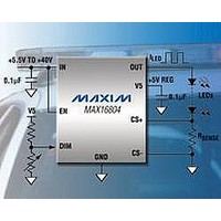
The dimming feature can be used for LED brightness
adjustment (see the Simplified Diagrams ) and theater
dimming. If an external PWM signal is used, the theater-
dimming effect can be achieved by varying the PWM
duty cycle. Figure 1 shows a simple circuit that imple-
ments theater dimming with a DC input signal.
The MAX16804 includes a fixed +5V output regulator
that delivers up to 2mA of load current throughout the
6.5V to 40V input voltage range. Connect a 0.1µF com-
pensation capacitor from V5 to ground. Shorting V5 to
ground disables the thermal shutdown. When EN is low,
V5 is off. V5 stays on during PWM dimming.
The MAX16804 enters a thermal-shutdown mode in the
event of overheating. This typically occurs in overload or
short-circuit conditions on the output. If the junction tem-
perature exceeds T
mal-protection circuitry turns off the series pass device.
The MAX16804 recovers from thermal-shutdown mode
once the junction temperature drops by 23°C (typ). The
part therefore protects itself by thermally cycling in the
event of a short-circuit or overload condition.
Figure 1. Theater Dimming
THEATER
DIMMING
SIGNAL
VIN
IN
EN
DIM
_______________________________________________________________________________________
J
= +155°C (typ), the internal ther-
MAX16804
GND
High-Voltage, 350mA LED Driver with
Thermal Protection
OUT
CS+
CS-
Analog and PWM Dimming Control
V5
+5V Regulator
+5V REG
0.1μF
R
LEDs
SENSE
The MAX16804 uses a sense resistor across CS+ and
CS- to set the LED current. The differential sense ampli-
fier connected across R
immunity and low-frequency noise rejection. The LED
current is given by
For proper operation, the minimum input voltage must
always be:
where V
series connected LEDs and ΔV
drop output voltage. The minimum operating voltage of
the device is +5.5V.
Figure 2 shows two-level brightness adjustment using
the MAX16804 with minimum external components. Set
the dimming level with a resistive divider connected to
DIM. See Equation 1 for details.
Figure 2. Two-Level Brightness Operation
STOP
TAIL
V
IN(MIN)
R1
R2
FT(MAX)
D2
D4
≥ V
D3
RSENSE(MAX)
D1
Applications Information
is the maximum forward voltage of all
Programming the LED Current
Input-Voltage Considerations
I
LED
Two Brightness Levels for
IN
EN
DIM
= V
SENSE
SENSE
MAX16804
+ V
GND
FT(MAX)
DO(MAX)
/R
provides ground-loop
TAIL/STOP Lights
SENSE
OUT
CS+
CS-
V5
+ ΔV
is the maximum
DO(MAX) (3)
LEDs
R
SENSE
(2)
7
Related parts for MAX16804ATP+
Image
Part Number
Description
Manufacturer
Datasheet
Request
R


Part Number:
Description:
MAX7528KCWPMaxim Integrated Products [CMOS Dual 8-Bit Buffered Multiplying DACs]
Manufacturer:
Maxim Integrated Products
Datasheet:
Part Number:
Description:
Single +5V, fully integrated, 1.25Gbps laser diode driver.
Manufacturer:
Maxim Integrated Products
Datasheet:
Part Number:
Description:
Single +5V, fully integrated, 155Mbps laser diode driver.
Manufacturer:
Maxim Integrated Products
Datasheet:
Part Number:
Description:
VRD11/VRD10, K8 Rev F 2/3/4-Phase PWM Controllers with Integrated Dual MOSFET Drivers
Manufacturer:
Maxim Integrated Products
Datasheet:
Part Number:
Description:
Highly Integrated Level 2 SMBus Battery Chargers
Manufacturer:
Maxim Integrated Products
Datasheet:
Part Number:
Description:
Current Monitor and Accumulator with Integrated Sense Resistor; ; Temperature Range: -40°C to +85°C
Manufacturer:
Maxim Integrated Products
Part Number:
Description:
TSSOP 14/A�/RS-485 Transceivers with Integrated 100O/120O Termination Resis
Manufacturer:
Maxim Integrated Products
Part Number:
Description:
TSSOP 14/A�/RS-485 Transceivers with Integrated 100O/120O Termination Resis
Manufacturer:
Maxim Integrated Products
Part Number:
Description:
QFN 16/A�/AC-DC and DC-DC Peak-Current-Mode Converters with Integrated Step
Manufacturer:
Maxim Integrated Products
Part Number:
Description:
TDFN/A/65V, 1A, 600KHZ, SYNCHRONOUS STEP-DOWN REGULATOR WITH INTEGRATED SWI
Manufacturer:
Maxim Integrated Products
Part Number:
Description:
Integrated Temperature Controller f
Manufacturer:
Maxim Integrated Products
Part Number:
Description:
SOT23-6/I�/45MHz to 650MHz, Integrated IF VCOs with Differential Output
Manufacturer:
Maxim Integrated Products
Part Number:
Description:
SOT23-6/I�/45MHz to 650MHz, Integrated IF VCOs with Differential Output
Manufacturer:
Maxim Integrated Products
Part Number:
Description:
EVALUATION KIT/2.4GHZ TO 2.5GHZ 802.11G/B RF TRANSCEIVER WITH INTEGRATED PA
Manufacturer:
Maxim Integrated Products