HFCT-5760TP Avago Technologies US Inc., HFCT-5760TP Datasheet - Page 2
HFCT-5760TP
Manufacturer Part Number
HFCT-5760TP
Description
Fiber Optic Transmitters, Receivers, Transceivers OC3 SFP IR -10 to +8 5 non-DMI
Manufacturer
Avago Technologies US Inc.
Datasheet
1.HFCT-5760TP.pdf
(18 pages)
Specifications of HFCT-5760TP
Function
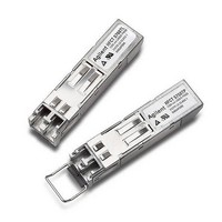
Singlemode Small Form Factor Pluggable Transceivers with LC Connector.
Product
Transceiver
Data Rate
155 Mbps
Wavelength
1300 nm
Maximum Rise Time
2.5 ns
Maximum Fall Time
2.5 ns
Operating Supply Voltage
3.1 V to 3.5 V
Maximum Operating Temperature
+ 85 C
Minimum Operating Temperature
- 10 C
Package / Case
SFP-20
Optical Fiber Type
TX/RX
Data Transfer Rate
155Mbps
Optical Rise Time
2.5ns
Optical Fall Time
2.5ns
Operating Temperature Classification
Commercial
Peak Wavelength
1360nm
Package Type
SFP
Operating Supply Voltage (min)
3.1V
Operating Supply Voltage (typ)
3.3V
Operating Supply Voltage (max)
3.5V
Operating Temp Range
-10C to 85C
Mounting
Snap Fit To Panel
Pin Count
20
For Use With
Singlemode Glass
Lead Free Status / RoHS Status
Lead free / RoHS Compliant


Functional Description
Receiver Section
Design
The receiver section for the HFCT-5760xxx
contains an InGaAs/InP photo detector and a
preamplifier mounted in an optical
subassembly. This optical subassembly is
coupled to a postamplifier/decision circuit on a
circuit board.
The postamplifier is ac coupled to the
preamplifier. The coupling capacitors are large
enough to pass the SONET/SDH test pattern at
155 Mb/s without significant distortion or
performance penalty. If a lower signal rate, or
a code which has significantly more low
frequency content is used, sensitivity, jitter and
pulse distortion could be degraded.
There is a filter function which limits the
bandwidth of the preamp output signal. The
filter is designed to bandlimit the preamp
output noise and thus improve the receiver
sensitivity.
Loss of Signal
The Loss of Signal (LOS) output indicates that
the optical input signal to the receiver does not
meet the minimum detectable level for
compliant signals. When LOS is high it
indicates loss of signal. When LOS is low it
indicates normal operation. The Loss of Signal
thresholds are set to indicate a definite optical
fault has occurred (eg., disconnected or broken
fiber connection to receiver, failed transmitter).
2
Transmitter Section
Design
A schematic diagram for the transceiver is
shown in Figure 1. The HFCT-5760xxx
incorporates an FP laser as its optical source.
All part numbers have been designed to be
compliant with IEC 825 eye safety requirements
under any single fault condition and CDRH
under normal operating conditions. The optical
output is controlled by a custom IC that
detects the laser output via the monitor
photodiode. This IC provides both dc and ac
current drive to the laser to ensure correct
modulation, eye diagram and extinction ratio
over temperature, supply voltage and operating
life.
Tx Fault
The HFCT-5760xxx module features a transmit
fault control signal output which when high
indicates a laser transmit fault has occurred
and when low indicates normal laser operation.
A transmitter fault condition can be caused by
deviations from the recommended module
operating conditions or by violation of eye
safety conditions. A fault is cleared by cycling
the Tx Disable control input.
Tx Disable
The HFCT-5760xxx accepts a transmit disable
control signal input which shuts down the
transmitter. A high signal implements this
function while a low signal allows normal laser
operation. In the event of a fault (eg., eye
safety circuit activated), cycling this control
signal resets the module. The Tx Disable
control should be actuated upon initialization of
the module.
Related parts for HFCT-5760TP
Image
Part Number
Description
Manufacturer
Datasheet
Request
R

Part Number:
Description:
TXRX SMF XFP 10BGE 2KM OC-192
Manufacturer:
Avago Technologies US Inc.
Datasheet:

Part Number:
Description:
Fiber Optics, Transceiver Module
Manufacturer:
Avago Technologies US Inc.

Part Number:
Description:
Fiber Optic Transmitters, Receivers, Transceivers SFP OC12 IR Standard Delatch
Manufacturer:
Avago Technologies US Inc.

Part Number:
Description:
Manufacturer:
Avago Technologies
Datasheet:

Part Number:
Description:
155 Mb/s Single Mode Laser Transceiver For Atm, Sonet OC-3/SDH STM-1 (L1.1)
Manufacturer:
Agilent Technologies, Inc.
Datasheet:
Part Number:
Description:
Fiber Optics, Evaluation Kit
Manufacturer:
Avago Technologies US Inc.
Datasheet:
Part Number:
Description:
Fiber Optics, Evaluation Kit
Manufacturer:
Avago Technologies US Inc.
Datasheet:
Part Number:
Description:
Fiber Optics, Evaluation Kit
Manufacturer:
Avago Technologies US Inc.
Datasheet:

Part Number:
Description:
Agilent HFCT-5215B/D 155 Mb/s Single Mode Laser Transceiver
Manufacturer:
Hewlett-Packard
Datasheet:

Part Number:
Description:
Agilent HFCT-5905E MT-RJ Duplex Single Mode Transceiver
Manufacturer:
HP [Agilent(Hewlett-Packard)]
Datasheet:

Part Number:
Description:
OPTOCOUPLER GATE DRV 2A 16-SOIC
Manufacturer:
Avago Technologies US Inc.
Datasheet:
Part Number:
Description:
OPTOCOUPLER 2CH 2.5A 16-SOIC
Manufacturer:
Avago Technologies US Inc.
Datasheet:

Part Number:
Description:
OPTOCOUPLER GATE DRV 0.4A 16SOIC
Manufacturer:
Avago Technologies US Inc.
Datasheet:

Part Number:
Description:
OPTOCOUPLER 2.0A 250KHZ 8-DIP
Manufacturer:
Avago Technologies US Inc.
Datasheet:

Part Number:
Description:
OPTOCOUPLER 2.0A 250KHZ GW 8-SMD
Manufacturer:
Avago Technologies US Inc.
Datasheet: