PT501 Sharp Microelectronics, PT501 Datasheet

Photodetector Transistors PT +- 6 DEG 800nm 2.5-80mA

PT501

Manufacturer Part Number
PT501
Description
Photodetector Transistors PT +- 6 DEG 800nm 2.5-80mA
Manufacturer
Sharp Microelectronics
Type
Phototransistorr
Datasheet

Specifications of PT501

Maximum Power Dissipation
75 mW
Maximum Dark Current
100 nA
Collector- Emitter Voltage Vceo Max
45 V
Fall Time
10 us
Maximum Operating Temperature
+ 125 C
Minimum Operating Temperature
- 25 C
Rise Time
10 us
Package / Case
TO-18
Voltage - Collector Emitter Breakdown (max)
45V
Current - Collector (ic) (max)
10mA
Current - Dark (id) (max)
100nA
Wavelength
800nm
Viewing Angle
12°
Power - Max
75mW
Mounting Type
Through Hole
Orientation
Top View
Lead Free Status / RoHS Status
Lead free / RoHS Compliant

Available stocks

Company
Part Number
Manufacturer
Quantity
Price
Part Number:
PT501
Manufacturer:
SHARP
Quantity:
56 000
Part Number:
PT501
Manufacturer:
SHARP
Quantity:
20 000
Part Number:
PT5011
Manufacturer:
OAUCH
Quantity:
2 000
Part Number:
PT5012
Manufacturer:
NIEC
Quantity:
1 000
Part Number:
PT5012
Quantity:
60
Part Number:
PT5016
Manufacturer:
Danfuss
Quantity:
1 000
Part Number:
PT5016
Quantity:
60
Part Number:
PT501A
Manufacturer:
KODENSHI
Quantity:
100
Part Number:
PT501A
Manufacturer:
SHARP/夏普
Quantity:
20 000
PT501/PT510
1. Narrow acceptance (
2. TO -18 type standard package
3. With base terminal : PT510
1. Optoelectronic switches, optoelectronic
2. Smoke detectors
3. Infrared applied systems
*1 For 10 seconds at the position of 1.3mm from the bottom face of can package
*2 E
“ In the absence of confirmation by device specification sheets, SHARP takes no responsibility for any defects that occur in equipment using any of SHARP's devices, shown in catalogs,
data books, etc. Contact SHARP in order to obtain the latest version of the device specification sheets before using any SHARP's device.”
*1
counters
Collector-emitter voltage
Emitter-collector voltage
Collector-base voltage
Emitter-base voltage
Collector power dissipation
Operating temperature
Storage temperature
Features
Applications
Absolute Maximum Ratings
Electro-optical Characteristics
*2
*2
Soldering temperature
e
Collector current
Collector dark current
Collector-emitter saturation voltage
Peak sensitivity wavelength
Response
time
: Irradiance by CIE standard light source A ( tungsten lamp )
Parameter
Parameter
Rise time
Fall time
: TYP. ± 6˚ )
Symbol
V
I
CE ( sat )
CEO
I
t
t
C
r
f
P
Symbol
V
V
V
V
T
T
T
P
CEO
ECO
CBO
EBO
V
V
I
V
R
opr
C
stg
sol
C
CE
CE
L
CE
= 1mA, E
= 100
= 5V, E
= 30V, E
= 2V, I
- 25 to + 125
- 55 to + 150
Conditions
PT501
C
( PT501 : 1k )
e
e
260
= 10mW/cm
= 10mW/cm
45
75
e
= 2mA,
6
-
-
= 0
TO-18 Type Narrow
Acceptance Phototransistor
45˚
Outline Dimensions
- 25 to + 125
- 55 to + 150
2
PT510
2
1.0
260
35
35
75
6
6
2.5
PT501
4.7
5.7
2
1
2
MIN.
( Ta = 25˚C )
2.5
± 0.1
MAX.
1
-
-
-
-
-
0.45
Glass
1 Collector
2 Emitter
lens
Unit
mW
˚C
˚C
˚C
V
V
V
V
PT501
PT510
PT501
PT510
PT501
PT510
45˚
2 x 10
TYP.
800
0.2
1.0
- 9
3
2.5
2
10
20
10
10
2
3
PT510
4.7
5.7
1
3
MAX.
± 0.1
PT501/PT510
2
MAX.
1 Collector ( Case )
2 Base
3 Emitter
10
Glass
( Unit : mm )
0.45
lens
2.5
( Ta = 25˚C )
1
-
-
-
-
-
- 7
Unit
mA
nm
A
V
s
s

Related parts for PT501

PT501 Summary of contents

Page 1

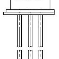
... T 260 260 sol Symbol Conditions 5V 10mW/ 30V CEO 1mA 10mW/ sat ) 2V 2mA PT501 : 100 PT501/PT510 ( Unit : mm ) ± 0.1 ± 0.1 4.7 4.7 Glass Glass lens lens PT501 PT510 0.45 0.45 2.5 2 1.0 MAX. 45˚ MAX. 5.7 5 Collector ( Case ) 1 Collector ...

Page 2

... Ambient temperature T Fig. 3 Relative Collector Current vs. Ambient Temperature 160 140 10mW/cm e 120 100 Ambient temperature 2 Fig. 2 Collector Dark Current vs 100 125 ( ˚ Fig.4-a Collector Current vs. Irradiance ˚ PT501/PT510 Ambient Temperature - 30V -10 - 100 125 ( ˚C ) Ambient temperature 25˚ mW/cm Irradiance PT501 ) ...

Page 3

... Fig. 8 Response Time vs. Base Resistance PT501/PT510 Collector-emitter Voltage MAX 10mW/ 7.5mW/ 5mW/ 2.5mW/ Collector-emitter voltage V CE 100 T = 25˚ 400 600 800 1000 1200 ( nm ) Wavelength 2mA 25˚ 0.5 0.2 0 100 200 500 1000 ( k Base resistance PT501 ) T = 25˚ PT510 ) 2000 5000 10000 ) ...

Page 4

... Test Circuit for Response Time Correspond to Fig. 7 Correspond to Fig Output Output PT501 has no base terminal. ) Fig.10 Collector-emitter Saturation Voltage vs. Irradiance 0 25˚C a 0.6 0.4 0 mW/cm ) Irradiance E e Please refer to the chapter “ Precautions for Use.” Fig. 9 Sensitivity Diagram - 30˚ Input ...

Related keywords