135D686X0100T6E3 Vishay, 135D686X0100T6E3 Datasheet - Page 10
135D686X0100T6E3
Manufacturer Part Number
135D686X0100T6E3
Description
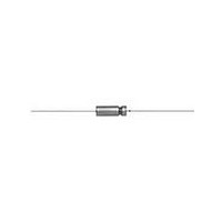
CAPACITOR TANT 68UF, 100V, 2.2OHM, AXIAL
Manufacturer
Vishay
Specifications of 135D686X0100T6E3
Capacitance
68uF
Tolerance (+ Or -)
20%
Voltage
100VDC
Mounting Style
Through Hole
Operating Temp Range
-55C to 200C
Esr
2.2Ohm
Construction
Axial
Dcl
10uA
Seal
Hermetic
Insulation
Sleeved - High Temp
Polarity
Polar
Failure Rate
Not Required
Product Length (mm)
21.03mm
Product Depth (mm)
Not Requiredmm
Product Height (mm)
Not Requiredmm
Product Diameter (mm)
10.32mm
Capacitance Tolerance
± 20%
Voltage Rating
100VDC
Capacitor Mounting
Through Hole
Termination Type
Axial Leaded
Leaded Process Compatible
Yes
Capacitor Terminals
Axial Leaded
Rohs Compliant
Yes
Lead Free Status / RoHS Status
Compliant


135D
Vishay
GUIDE TO APPLICATION
1.
2.
www.vishay.com
10
AC Ripple Current: Subjecting a capacitor to an AC
voltage causes an AC current to flow through it. The
amplitude of the current is dependent on the
impedance of the capacitor at the frequency of the
applied signal:
where:
This current causes heating in the capacitor because of
I
applied frequency). This heating or power dissipation,
is one of the limiting factors of the capacitor’s ripple
current rating.
These power dissipation ratings are based on a
calculated + 50 °C internal temperature rise in still air.
The maximum alowable ripple currents given in the
“Standard and Extended Ratings Tables” are based on
these ratings and the maximum equivalent series
resistance at that frequency.
The relationship is written as follows:
Therefore:
AC Ripple Voltage: In operation, the peak voltage
across the capacitor (DC working voltage plus peak
ripple voltage) must not exceed the rated working
voltage of the capacitor. The DC component of the
applied voltage should be sufficiently large to prevent
polarity reversal in excess of 3 V at + 85 °C or 2 V at
125 °C.
where:
where:
2
I = Ripple current
V = Applied AC voltage
Z = Impedance of capacitor (frequency dependent)
P = Maximum power
I = Maximum ripple current
R = Equivalent series resistance
R is in Ω
P is in W
I is in A
R losses (R is the equivalent series resistance at the
CASE CODE
C
K
F
T
RMS
Wet Tantalum Capacitors Tantalum-Case with Glass-to-Tantalum
P
I
I
=
=
=
AT + 25 °C (W) IN FREE AIR
MAXIMUM PERMISSIBLE
I
V
Z
2
R
POWER DISSIPATION
P
R
Hermetic Seal for - 55 °C to + 200 °C Operation
For technical questions, contact:
1.00
1.55
1.75
1.95
tantalum@vishay.com
There will be a point at the lower frequency and
capacitance values when the peak AC voltage will be
the limiting factor on the ripple current - not its heating
effects.
For example:
where:
Therefore:
and
Therefore, the peak voltage of the capacitor is the
limiting factor for the ripple current and can be
calculated as follows:
or
Max I
Given a 25 µF, 8 V capacitor in the “C” case code and
assuming a ripple current application at a frequency
of 120 Hz, the total maximum allowable peak to peak
voltage at + 25 °C is:
8 V
In order to allow the full swing of 11 V
exceed rated forward or rated reverse, a DC bias of
2.5 V is assumed to be applied.
From the ”Standard Ratings Table”, the maximum
ripple current at 40 kHz is 0.820 A. Compensating for
the lower frequency from the “Ripple Current
Multipliers” tables:
I
This current rating is calculated strictly on the basis of
maximum power dissipation. Now calculate what
impressed voltage this amount of current will cause
across this capacitor.
Assuming a sinusoidal voltage, calculate the rated
peak to peak current:
ESR = 4 Ω (from “Standard Ratings” table)
RMS
X
I
pp
C
F
+ 3 V
(120 Hz) = 0.820 A x 0.6 = 0.492 A
=
=
pp
Z
V
C 120Hz
I
2πfC
V
pp impressed
RMS
=
0.206
-------------- -
(
Z
2 2
pp impressed
1
(
C
V
---------------------------------------- -
R
(
Cpp
=
×
= 11 V
=
)
=
2 2
=
=
(
2 π ( ) 120
4 ( )
74.1 V
allowed
Z
0.073 A
(
C
2
=
)
pp
(
)
(
+
=
=
ESR
0.492
(
pp
1.39 A
I
53.1
pp
RMS
) 25
)
1
>
(
)
×
=
2
11 V
×
)
Z
+
2
------------------
53.3 Ω
11.0 V
2.828
at 120 Hz
C
×
pp
Document Number: 40024
=
(X
10
(
pp
×
120 Hz
53.3 Ω
C (120 Hz)
–
53.3 Ω
6
=
)
Revision: 15-Nov-10
=
=
1.39 A
0.206 A
)
53.1 Ω
)
2
RMS
pp
pp
pp
and not
Related parts for 135D686X0100T6E3
Image
Part Number
Description
Manufacturer
Datasheet
Request
R

Part Number:
Description:
357-036-542-201 CARDEDGE 36POS DL .156 BLK LOPRO
Manufacturer:
Vishay
Datasheet:
Part Number:
Description:
357-036-542-201 CARDEDGE 36POS DL .156 BLK LOPRO
Manufacturer:
Vishay
Datasheet:
Part Number:
Description:
357-036-542-201 CARDEDGE 36POS DL .156 BLK LOPRO
Manufacturer:
Vishay
Datasheet:
Part Number:
Description:
357-036-542-201 CARDEDGE 36POS DL .156 BLK LOPRO
Manufacturer:
Vishay
Datasheet:
Part Number:
Description:
357-036-542-201 CARDEDGE 36POS DL .156 BLK LOPRO
Manufacturer:
Vishay
Datasheet:
Part Number:
Description:
357-036-542-201 CARDEDGE 36POS DL .156 BLK LOPRO
Manufacturer:
Vishay
Datasheet:
Part Number:
Description:
357-036-542-201 CARDEDGE 36POS DL .156 BLK LOPRO
Manufacturer:
Vishay
Datasheet:
Part Number:
Description:
357-036-542-201 CARDEDGE 36POS DL .156 BLK LOPRO
Manufacturer:
Vishay
Datasheet:
Part Number:
Description:
357-036-542-201 CARDEDGE 36POS DL .156 BLK LOPRO
Manufacturer:
Vishay
Datasheet:
Part Number:
Description:
357-036-542-201 CARDEDGE 36POS DL .156 BLK LOPRO
Manufacturer:
Vishay
Datasheet:
Part Number:
Description:
357-036-542-201 CARDEDGE 36POS DL .156 BLK LOPRO
Manufacturer:
Vishay
Datasheet:
Part Number:
Description:
357-036-542-201 CARDEDGE 36POS DL .156 BLK LOPRO
Manufacturer:
Vishay
Datasheet:
Part Number:
Description:
357-036-542-201 CARDEDGE 36POS DL .156 BLK LOPRO
Manufacturer:
Vishay
Datasheet:
Part Number:
Description:
357-036-542-201 CARDEDGE 36POS DL .156 BLK LOPRO
Manufacturer:
Vishay
Datasheet:
Part Number:
Description:
357-036-542-201 CARDEDGE 36POS DL .156 BLK LOPRO
Manufacturer:
Vishay
Datasheet: