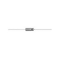
135D686X0100T6E3 Vishay, 135D686X0100T6E3 Datasheet - Page 8

135D686X0100T6E3
Manufacturer Part Number
135D686X0100T6E3
Description
CAPACITOR TANT 68UF, 100V, 2.2OHM, AXIAL
Manufacturer
Vishay
Specifications of 135D686X0100T6E3
Capacitance
68uF
Tolerance (+ Or -)
20%
Voltage
100VDC
Mounting Style
Through Hole
Operating Temp Range
-55C to 200C
Esr
2.2Ohm
Construction
Axial
Dcl
10uA
Seal
Hermetic
Insulation
Sleeved - High Temp
Polarity
Polar
Failure Rate
Not Required
Product Length (mm)
21.03mm
Product Depth (mm)
Not Requiredmm
Product Height (mm)
Not Requiredmm
Product Diameter (mm)
10.32mm
Capacitance Tolerance
± 20%
Voltage Rating
100VDC
Capacitor Mounting
Through Hole
Termination Type
Axial Leaded
Leaded Process Compatible
Yes
Capacitor Terminals
Axial Leaded
Rohs Compliant
Yes
Lead Free Status / RoHS Status
Compliant
135D
Vishay
6.2. The dissipation factor may be calculated from the
7.
7.1 The maximum leakage current for any capacitor shall
Note
•
8.
9.
9.1 Following the life test, the capacitors shall be returned
www.vishay.com
8
Leakage current varies with applied voltage. See graph next
column for the appropriate adjustment factor
equivalent series resistance and capacitance values as
shown:
where:
At 120 Hz, the above equation becomes:
For example, percent dissipation factor of a 30 µF, 6 V
capacitor, which has a maximum ESR of 4.0 Ω at
+ 25 °C and 120 Hz, would be calculated as shown:
Leakage Current: Measurements shall be made at the
applicable rated working voltage at + 25 °C ± 5 °C
through application of a steady source of power, such
as a regulated power supply. A 1000 Ω resistor to limit
the charging current shall be conected in series with
each capacitor under test. Rated working voltage shall
be applied to capacitors for 5 minutes before making
leakage current measurements.
not exceed the maximum value in mA listed in the
“Standard and Extended Ratings Table” for each
capacitor.
Low Temperature Impedance: The impedance of any
capacitor at - 55 °C at 120 Hz, shall not exceed the
values given in the “Standard and Extended Ratings
tables”.
Life Test: Capacitors are capable of withstanding a
2000 h life test at a temperature of + 85 °C or + 125 °C
at the applicable rated DC working voltage.
to 25 °C ± 5 °C. The leakage current, measured at the
+ 85 °C rated voltage, shall not be in excess of the
original requirement; the capacitance value shall not
exceed 150 % of the initial requirement; the
capacitance value shall not change more than 10 %
from the initial measurement.
DF
DF = Dissipation Factor in %
R = ESR in Ω
C = Capacitance in µF
f = Frequency in Hz
=
2π
---------------------------------------------
×
120
10
Wet Tantalum Capacitors Tantalum-Case with Glass-to-Tantalum
DF
×
4
DF
4
×
=
=
30
2πfRC
----------------- -
R C
-------------- -
13.26
10
=
×
Hermetic Seal for - 55 °C to + 200 °C Operation
4
4
--------------- -
13.26
×
For technical questions, contact:
30
=
9.05 %
tantalum@vishay.com
9.3 Capacitors are capable of withstanding life test at the
9.4 Following the life test, the capacitors shall be returned
TYPICAL LEAKAGE CURRENT FACTOR
RANGE
following conditions:
to + 25 °C ± 5 °C. The leakage current, at the rated
voltage shall not exceed 200 % of the original
requirement or ± 10 µA, whichever is greater; the
equivalent series resistance shall not be greater than
200 % of the original requirement; the capacitance
value shall not increase by more than 10 % or decrease
by more than 20 % from the initial measurement.
TEMPERATURE
0.09
0.08
0.07
0.06
0.05
0.04
0.03
0.02
0.01
+ 175 °C
+ 175 °C
+ 200 °C
1.0
0.9
0.8
0.7
0.6
0.5
0.4
0.3
0.2
0.1
0
10
PERCENT OF RATED VOLTAGE
20 30 40 50 60
HOURS
2000
300
300
Document Number: 40024
% RATED VOLTAGE
Revision: 15-Nov-10
70 80
50
65
60
90 100


