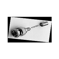
031-71013-RFX Amphenol, 031-71013-RFX Datasheet - Page 3

031-71013-RFX
Manufacturer Part Number
031-71013-RFX
Description
Manufacturer
Amphenol
Type
BNCr
Specifications of 031-71013-RFX
Gender
PL
Body Style
Straight
Terminate To
Coaxial Cable
Mounting Style
Cable
Termination
Crimp
Operating Frequency
0 to 4
Body Plating
Nickel
Contact Plating
Gold
Contact Material
Brass
Impedance
75Ohm
Operating Temp Range
-65C to 165C
Insulation Material
Polytetrafluoroethylene
Body Material
Brass
Lead Free Status / RoHS Status
Compliant
Assembly Instructions-C26
BNC
Step 1
Amphenol Corporation Tel: 800-627-7100
3-PIECE CRIMP PLUGS
Step 1 Strip cable jacket, braid, and dielec-
tric to dimensions in table above. [for RG-
62,71,210/U cable, trim an additional
.039"(1.0mm) of insulation off center conduc-
tor and add bushing] All cuts are to be sharp
and square.
Important: Do not nick braid, dielectric, and
center conductor. Slide outer ferrule onto
cable as shown.
36650-1003
36650-3RFX
36875
68175-1003
68175-1005
68175-1011
68175-11RFX
68175-5RFX
31-242
31-242-RFX
31-315
31-315-RFX
31-315-1005
31-320
31-320-RFX
31-320-1006
31-321
31-321-RFX
31-321-1000
31-321-10RFX
31-325
31-326
31-326-RFX
31-4320
31-4321
31-4411
31-4427
31-5558-RFX
31-5800
31-5900
For RG-174, 179, 187, 188, 316/U cables only, slit jacket back .100"(2.5mm)
as shown. Before attaching center contact, slide metal spacer/TFE sleeve
(not shown) over cable dielectric and under braid. The center contact
should butt against the dielectric and TFE sleeve.
Amphenol
Number
BNC Plug
BNC Plug
BNC Plug
BNC Plug
BNC Plug
BNC Plug
BNC Plug
BNC Plug
BNC Plug
BNC Plug
BNC Plug
BNC Plug
BNC Plug
BNC Plug
BNC Plug
BNC Plug
BNC Plug
BNC Plug
BNC Plug
BNC Plug
BNC Plug
BNC Plug
BNC Plug
BNC Plug
BNC Plug
BNC Plug
BNC Plug
BNC Plug
BNC Plug
BNC Plug
Connector
Type
Belden 82907, 88240
89907, Plenum 58
Plenum 58
55, 142, 223, 400
Belden 9259
59 (20AG CC)
Belden 1560A, 82259,
89259, Plenum 59, 62
Plenum 59, 62
59 (20GA CC)
179, 187
179, 187
174, 188, 316
174, 188, 316
Dbl. Br. 316
58, 141
58A, 141, 142A
Belden 9907, 89907
59, 62
59, 62
Belden 8281, 88281
Belden 8281
Belden 8218
55, 142, 223
55, 142, 223, 400
58, 141
59, 62
Belden 8213
142, 400
6 Type (.314OD)
58, 141, PL-58
59, 62, 59 (20GA CC),
Plenum -59, 62
a
b
RG-/U
Cable
outer ferrule
c
Step 2 Flare slightly end of cable braid as
shown to facilitate insertion of inner ferrule.
Important: Do not comb out braid
Place contact on cable center conductor so
that it butts against cable dielectric. Crimp
contact in place using Die Set Cavity indicat-
ed in table above. When using RG-62, 71,
210 cable, install bushing over center con-
ductor before installing contact.
Step 2
contact must butt against cable dielectric
.068(1.7)
.068(1.7)
.068(1.7)
.068(1.7)
.068(1.7)
.068(1.7)
.068(1.7)
.068(1.7)
.068(1.7)
.068(1.7)
.068(1.7)
.068(1.7)
.068(1.7)
.068(1.7)
.068(1.7)
.068(1.7)
.068(1.7)
.068(1.7)
.068(1.7)
.068(1.7)
.068(1.7)
.068(1.7)
.068(1.7)
.068(1.7)
.068(1.7)
.100(2.5)
.068(1.7)
.068(1.7)
.068(1.7)
.068(1.7)
Cavity for
Contact
bushing
used with RG-62, 71, 210 cable only
Outer Ferrule
.178(4.5)
.213(5.4)
.213(5.4)
.255(6.5)
.255(6.5)
.255(6.5)
.255(6.5)
.255(6.5)
.178(4.5)
.178(4.5)
.178(4.5)
.178(4.5)
.178(4.5)
.213(5.4)
.213(5.4)
.213(5.4)
.255(6.5)
.255(6.5)
.324(8.2)
.324(8.2)
.178(4.5)
.213(5.4)
.213(5.4)
.213(5.4)
.255(6.5)
.429(10.9)
.213(5.4)
.324(8.2)
.213(5.4)
.255(6.5)
Cavity for
300
* for pneumatic crimp tool 227-60, use die sets indicated in this column.
male contact
Hex Crimp Data
Tool 227-944*
227-1221-9
227-1221-11
227-1221-11
227-1221-13
227-1221-13
227-1221-13
227-1221-13
227-1221-13
227-1221-9
227-1221-9
227-1221-9
227-1221-9
227-1221-9
227-1221-11
227-1221-11
227-1221-11
227-1221-13
227-1221-13
227-1221-32
227-1221-32
227-1221-9
227-1221-11
227-1221-11
227-1221-11
227-1221-13
227-1221-25
227-1221-11
227-1221-32
227-1221-11
227-1221-13
Die Set for
.
outer ferrule should butt here
Tool Number
CTL Series
Step 3
CTL-2
CTL-1
CTL-1
CTL-1
CTL-1
CTL-1
CTL-1
CTL-1
CTL-2
CTL-2
CTL-2
CTL-2
CTL-2
CTL-1
CTL-1
CTL-1
CTL-1
CTL-1
CTL-2
CTL-2
CTL-2
CTL-1
CTL-1
CTL-1
CTL-1
CTL-3
CTL-1
CTL-2
CTL-1
CTL-1
Step 3 Install cable assembly into body
assembly so that inner ferrule portion slides
under braid. Push cable assembly forward
until contact snaps into place in insulator.
Slide outer ferrule over braid and up against
connector body. Crimp outer ferrule using
Die Set Cavity specified in table above.
plug body assembly
.593(15.1)
.630(16.0)
.593(15.1)
.593(15.1)
.593(15.1)
.593(15.1)
.630(16.0)
.630(16.0)
.593(15.1)
.590(15.0)
.593(15.1)
.593(15.1)
.593(15.1)
.593(15.1)
.630(16.0)
.593(15.1)
.593(15.1)
.630(16.0)
.593(15.1)
.630(16.0)
.593(15.1)
.593(15.1)
.593(15.1)
.593(15.1)
.593(15.1)
.650(16.5)
.593(15.1)
.630(16.0)
.593(15.1)
.593(15.1)
Stripping Dimensions, inches (mm)
crimp here
a
cable dielectric must butt insulator
Amphenol
.250(6.4)
.319(8.1)
.250(6.4)
.250(6.4)
.250(6.4)
.250(6.4)
.303(7.7)
.303(7.7)
.250(6.4)
.323(8.2)
.250(6.4)
.250(6.4)
.250(6.4)
.250(6.4)
.303(7.7)
.250(6.4)
.250(6.4)
.303(7.7)
.250(6.4)
.303(7.7)
.250(6.4)
.250(6.4)
.250(6.4)
.250(6.4)
.250(6.4)
.250(6.4)
.250(6.4)
.303(7.7)
.250(6.4)
.250(6.4)
www.amphenolrf.com
b
.156(4.0)
.157(4.0)
.156(4.0)
.156(4.0)
.156(4.0)
.156(4.0)
.157(4.0)
.157(4.0)
.156(4.0)
.118(3.0)
.156(4.0)
.156(4.0)
.156(4.0)
.156(4.0)
.156(4.0)
.156(4.0)
.156(4.0)
.156(4.0)
.156(4.0)
.156(4.0)
.156(4.0)
.156(4.0)
.156(4.0)
.156(4.0)
.156(4.0)
.156(4.0)
.156(4.0)
.156(4.0)
.156(4.0)
.156(4.0)
c
®


