DR-TRC105-450-EV RFM, DR-TRC105-450-EV Datasheet
DR-TRC105-450-EV
Specifications of DR-TRC105-450-EV


Related parts for DR-TRC105-450-EV


DR-TRC105-450-EV Summary of contents
Page 1
... DR-TRC105-DK Development Kit User’s Guide www.RFM.com ©2009-2010 by RF Monolithics, Inc. DR-TRC105-304-DK DR-TRC105-315-DK DR-TRC105-345-DK DR-TRC105-372-DK DR-TRC105-390-DK DR-TRC105-403-DK DR-TRC105-434-DK DR-TRC105-450-DK Technical support +1.800.704.6079 E-mail: info@rfm.com Page DR-TRC105-DK - 04/05/10 ...
Page 2
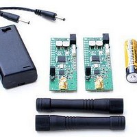
... Introduction The DR-TRC105 series development kits can be used to evaluate TRC105 radio technology, and to prototype applications that will use the TRC105 RFIC. These development kits include the necessary hardware, firmware and utility software to support efficient TRC105 evaluation and system development. This user’s guide covers ...
Page 3
... DR-TRC105 development kits are designed to facilitate the configuration of all TRC105 transmitter, receiver and interface functions, and to support application firmware and system development. The development kits can be controlled using the RFIC Design Assistant utility software. Two-way communication link testing is also supported by the data terminal program built into the RFIC Design Assistant utility ...
Page 4
... Figure 2 - DR-TRC105-DK Interface Board Connectors and Controls Figure 2 shows the locations of the interface board DC power connectors, user controls and LED indicators. Normally an interface board is powered from one of the 4.5 volt universal wall-plug power supplies provided in the development kit, as shown in the left panel of Figure 3 ...
Page 5
... POWER ON LED, the serial communication interface circuitry and the radio board. Note that there is a small current draw from the regulator when the power switch is in the off position, and this will eventually discharge a 9 volt battery left installed ...
Page 6
... On the transmitting board, you should observe the red Packet Error LED flashing. This indicates that the transmitter sent a packet but did not receive an acknowledgment back from the “receiving” radio board. www.RFM.com ©2009-2010 by RF Monolithics, Inc. Technical support +1.800.704.6079 E-mail: info@rfm.com Page DR-TRC105-DK - 04/05/10 ...
Page 7
... Windows® as follows: Start > Settings > Control Panel > System > Hardware > Device Manager > Ports (COM & LPT). 5. Select the TRC105 from the TRC drop-down menu as shown in Figure 8. This will launch the TRC105 multi-tab dialog window as shown in Figure 9 6. Select the Main Menu tab and click on the Read Configuration button. A hex dump of the current TRC105 configuration parameters should appear in the text box above the button as shown in Figure 9 ...
Page 8
... Figure 7 - Starting RFIC Design Assistant Figure 8 - Selecting TRC105 Operation www.RFM.com ©2009-2010 by RF Monolithics, Inc. Figure 9 - Read Configuration Test Technical support +1.800.704.6079 E-mail: info@rfm.com Page DR-TRC105-DK - 04/05/10 ...
Page 9
... Figure 10 - DR-TRC105 Radio Board LED Indicators Radio Board Details The DR-TRC105 radio board LED indicator names and locations are shown in Figure 10. Table 2 summarizes the functions of the DR-TRC105 radio board connectors, user controls and LED indicators. Component Designator I/O Connector J2 Battery Connector ...
Page 10
... DR-TRC105-315-EV DR-TRC105-345-EV DR-TRC105-372-EV DR-TRC105-390-EV DR-TRC105-403-EV DR-TRC105-434-EV DR-TRC105-450-EV Power: +10 dBm Frequency Deviation: ±50 kHz Data Rate: 25 kb/s Receiver Baseband Bandwidth: 100 kHz The radio board is also initially configured in Receive Continuous Mode (see the TRC105 datasheet for an explanation of continuous mode, buffered data mode, packet data mode, etc ...
Page 11
... Figure 11 - DR-TRC105 Radio Board TX Power Adjustment Two AA battery packs are supplied in the development kit to power the radio boards when they are removed from the interface boards, as shown in Figure 12. Alternately, a regulated power supply in the range of 2.7 to 3.6 volts can be used to power the radio boards ...
Page 12
... Figure 13 - DR-TRC105 Radio Board Test Points Referring to Figure 13, test points are provided to monitor signals to/from the TRC105 RFIC in real time. Test point details are listed in Table 3: PCB Symbol SCK SPI clock SDO SPI data from TRC105 SDI SPI data to the TRC105 ...
Page 13
... Figure 14 - DR-TRC103/105 Interface Board Details Interface Board Details Figure 14 and Table 4 summarizes the functions of the DR-TRC103/105 interface board connectors, user controls and LED indicators. Also note that many of the radio board test points are duplicated on the edge of the interface board prototyping area. ...
Page 14
... On the first press, the Terminal The message RX MODE is output on the serial connection. On the second button press, the message TERM MODE is output on the serial connection. Table 5 - DR-TRC105 Firmware Switch-selectable Modes www.RFM.com ©2009-2010 by RF Monolithics, Inc. Figure 15 - Mode Switches and LEDs Mode Selection Technical support +1 ...
Page 15
... Terminal Mode Receive 02msg030D0A Table 6 - DR-TRC105 Firmware Serial Commands Figure 16 - DR-TRC103/105 Interface Board Connector for Firmware Development Support Custom Firmware Development Support The 10-pin programming header on the interface board is compatible with the Silicon Labs development tools for the C8051F310 microcontroller. This allows the user to develop and test custom firmware for use with the TRC105 ...
Page 16
... Radio Board Interface Connector Figure 17 shows the pin numbering detail of connector J2 on the edge of the DR- TRC105 radio boards. Figure 17 can be used with the schematics in the last section of this manual to design a custom application interface for the radio boards. Note that all signal levels into and out of this connector are nominally 3 volt logic level ...
Page 17
... RF Monolithics, Inc. Technical support +1.800.704.6079 E-mail: info@rfm.com Page DR-TRC105-DK - 04/05/10 ...
Page 18
... RF Monolithics, Inc. Technical support +1.800.704.6079 E-mail: info@rfm.com Page DR-TRC105-DK - 04/05/10 ...
Page 19
... RF Monolithics, Inc. Technical support +1.800.704.6079 E-mail: info@rfm.com Page DR-TRC105-DK - 04/05/10 ...
Page 20
... RF Monolithics, Inc. Technical support +1.800.704.6079 E-mail: info@rfm.com Page DR-TRC105-DK - 04/05/10 ...
Page 21
... RF Monolithics, Inc. Technical support +1.800.704.6079 E-mail: info@rfm.com Page DR-TRC105-DK - 04/05/10 ...
Page 22
... RF Monolithics, Inc. Technical support +1.800.704.6079 E-mail: info@rfm.com Page DR-TRC105-DK - 04/05/10 ...
Page 23
... RF Monolithics, Inc. Technical support +1.800.704.6079 E-mail: info@rfm.com Page DR-TRC105-DK - 04/05/10 ...
Page 24
... RF Monolithics, Inc. Technical support +1.800.704.6079 E-mail: info@rfm.com Page DR-TRC105-DK - 04/05/10 ...
Page 25
... RF Monolithics, Inc. Technical support +1.800.704.6079 E-mail: info@rfm.com Page DR-TRC105-DK - 04/05/10 ...
Page 26
... RF Monolithics, Inc. Technical support +1.800.704.6079 E-mail: info@rfm.com Page DR-TRC105-DK - 04/05/10 ...
Page 27
... RF Monolithics, Inc. Technical support +1.800.704.6079 E-mail: info@rfm.com Page DR-TRC105-DK - 04/05/10 ...