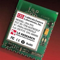
ZMXM-400-1-B CEL, ZMXM-400-1-B Datasheet - Page 8

ZMXM-400-1-B
Manufacturer Part Number
ZMXM-400-1-B
Description
Zigbee / 802.15.4 Modules & Development Tools Matrix Zigbee 10mW 10MW Module
Manufacturer
CEL
Datasheet
1.ZMXM-400-KIT-2.pdf
(13 pages)
Specifications of ZMXM-400-1-B
Wireless Frequency
2405 MHz to 2480 MHz
Interface Type
UART
Operating Voltage
3.6 V
Output Power
100 mW
Antenna
PCB Trace
Operating Temperature Range
- 45 C to + 125 C
Lead Free Status / RoHS Status
Lead free / RoHS Compliant
PCB PAD LAYOUT
PCB KEEP-OUT AREAS
Note:
0.080
Matrix Module 10mW
Matrix modules should be mounted so the antenna is overhanging the board edge. This will provide the best antenna performance
for the PCB trace antenna. It is also recommended to have a ground plane on the host board underneath the rest of the module,
up to the recommended PCB edge. This will improve the antenna performance by increasing the overall ground plane.
Traces can be run underneath the Matrix module on the host PCB as long a there is an uninterrupted ground plane on one layer as
well. CEL can arrange guidance and help with the host PCB layout.
0.085
PIN 1
0.105
0.175
0.990
0.270
PIN 1
0.080
0.455
Dimensions in inches. Tolerances = +/-0.005” unless otherwise noted.
0.100 Pitch Typ
0.005
Dimensions in inches. Tolerances = +/-0.005” unless otherwise noted.
PIN 24
Exposed PCB Trace
Top Layer Keep-Out Area
0.455
PIN 24
0.085
0.105
Recommended
Host PCB Edge
Minimum PCB Trace, Plane and Component
Keep-Out Area, All Layers
0.080 Typ 24 Pads
0.085 Typ 24 Pads
0.185
Matrix Module 100mW
PIN 1
0.175
0.990
0.270
ZMXM-400 Series
PIN 24
Exposed PCB Trace
Top Layer Keep-Out Area
Minimum PCB Trace,
Plane & Component
Keep-Out Area, All Layers
Recommended
Host PCB Edge


