ATAB5283 Atmel, ATAB5283 Datasheet - Page 2
ATAB5283
Manufacturer Part Number
ATAB5283
Description
WiFi / 802.11 Modules & Development Tools LF Rx Board 1 channel (TPMS)
Manufacturer
Atmel
Series
Smart RFr
Type
LF Antenna Driverr
Datasheet
1.ATAB5276.pdf
(17 pages)
Specifications of ATAB5283
Contents
2 Boards, Antenna, Cables, Power Supply, Software
Lead Free Status / Rohs Status
Lead free / RoHS Compliant
For Use With/related Products
ATAB5278


2.1
2.2
3. Host Software Controlling the ATAB5276 Transmitter Board
2
Components Included
Equipment Needed
ATAK5276-83
Host software is needed to control the transmitter board via the microcontroller on the base
board. The software is installed by executing a self-extracting setup file contained on the
included CD-ROM (see
Upon execution of the demonstration software, the setup menu is displayed (see
page
Depending on the mode selection, patterns can be sent in single-operation or loop-operation
mode. Pattern data to be sent can either be loaded by clicking on load pattern, or by directly edit-
ing the table. The index box to the left of the table shows the index number of the OFF/ON timing
step located in the top row of the table. A maximum of 100 OFF/ON timing steps can be speci-
fied and saved to the AVR
new data file.
To demonstrate ATA5276 with ATA5283, an appropriate data file ATA5283.dat is loaded by
default. That file includes the preamble protocol for waking up the receiver; followed by modula-
tion data, switching on the LED indicator on the receiver board. With the continuous carrier
mode selection, the field can be switched on steadily (this feature is useful for antenna evalua-
tion or field strength measurements).
• ATAB5276 demonstrator board patched onto a microcontroller base board
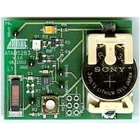
• ATAB5283 receiver board, inclusive Li battery (optionally, the ATAB5282 receiver board)
• Antenna module
• Serial RS232 interface cable
• Two cables for DC power supply
• CD-ROM installation software and documentation
• Host PC with Windows
• Power supply 8V to 24V DC 2A (alternative 8V to 24V DC 1A with capacitor 2000 µF/20V at
output)
3). Clicking send causes serial data patterns to be sent via the DIO line to the transmitter.
Section 5. ”Demonstrator: Getting Started” on page
®
®
95 or higher
microcontroller. Specially composed patterns may be saved into a
11).
4857C–AUTO–07/06
Figure 3-1 on
Related parts for ATAB5283
Image
Part Number
Description
Manufacturer
Datasheet
Request
R

Part Number:
Description:
DEV KIT FOR AVR/AVR32
Manufacturer:
Atmel
Datasheet:

Part Number:
Description:
INTERVAL AND WIPE/WASH WIPER CONTROL IC WITH DELAY
Manufacturer:
ATMEL Corporation
Datasheet:
Part Number:
Description:
Low-Voltage Voice-Switched IC for Hands-Free Operation
Manufacturer:
ATMEL Corporation
Datasheet:
Part Number:
Description:
MONOLITHIC INTEGRATED FEATUREPHONE CIRCUIT
Manufacturer:
ATMEL Corporation
Datasheet:
Part Number:
Description:
AM-FM Receiver IC U4255BM-M
Manufacturer:
ATMEL Corporation
Datasheet:
Part Number:
Description:
Monolithic Integrated Feature Phone Circuit
Manufacturer:
ATMEL Corporation
Datasheet:
Part Number:
Description:
Multistandard Video-IF and Quasi Parallel Sound Processing
Manufacturer:
ATMEL Corporation
Datasheet:
Part Number:
Description:
High-performance EE PLD
Manufacturer:
ATMEL Corporation
Datasheet:
Part Number:
Description:
8-bit Flash Microcontroller
Manufacturer:
ATMEL Corporation
Datasheet:
Part Number:
Description:
2-Wire Serial EEPROM
Manufacturer:
ATMEL Corporation
Datasheet: