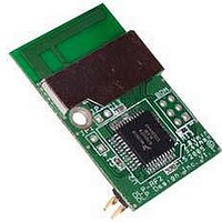
DLP-RF2 DLP Design Inc, DLP-RF2 Datasheet

DLP-RF2
Specifications of DLP-RF2
Related parts for DLP-RF2
DLP-RF2 Summary of contents
Page 1
... Interface to an external serial host microcontroller/ DSP/FPGA, etc. is accomplished via a simple 2-wire (RX, TX, and ground) interface. The SIPP firmware in the DLP-RF2-Z resides at the application layer and is based on Freescale’s SMAC. The SIPP firmware provides basic access to DLP-RF2-Z functionality: Packet receive and transmit, transceiver settings, EEPROM access, etc ...
Page 2
... ID (packet destination), the source transceiver ID (packet origin), and a command byte. As shipped from DLP Design, the DLP-RF2-Z has more than one DLP-RF2 used in a system, then this ID must be changed to a value higher than 2. Upon reset or power up, the ID is read from non-volatile EEPROM memory. If JP1 is shorted at power up (or before a reset), the default ID for the DLP-RF2-Z is set to 2 and other transceiver settings are also returned to a default state in the EEPROM ...
Page 3
... Reserved EEPROM Locations The EEPROM memory is a feature of the SIPP firmware and, as such, is only available if using the DLP-RF2-Z with its firmware as shipped from DLP Design. The EEPROM memory used by the SIPP firmware consists of a block of 32 bytes that reside within the Flash program memory of the MC9S08GT60. The first 10 bytes (0-9) and the last byte (31) are reserved for storing transceiver settings and checksum. Bytes 10 through 30 (user area) are available for use by user’ ...
Page 4
... Checksum 2.3 Command Set This Command Set is a feature of the SIPP firmware and, as such, is only available if using the DLP-RF2-Z with its firmware as shipped from DLP Design. Rev 1.8 (November 2005) Options Range: 1-65,535 0-15 (2.405GHz to 2.480GHz) 0-15 (-16.6 to +3.5dBm into the balun) Range: 1-65,535 ...
Page 5
... Command Packets. In the case of the DLP-RF2-Z, the host is the user-supplied serial host microcontroller/DSP/FPGA, etc Command Packet is received by the DLP-RF2-Z via the serial host interface with a destination ID that matches the ID stored in the EEPROM of the DLP-RF2-Z, then the MC9S08GT60 will process the packet and reply to the serial host controller. If the ID in the packet does not match the ID stored in EEPROM, then the packet is intended for a different destination and is transmitted via the transceiver ...
Page 6
... Data Bytes: Current I/O pin state (A6, B6:0), Bit-field with bits set for the port pins that changed state (A6, B6:0) Check-in from DLP-RF2-Z due to wake from sleep (no data) Measured energy data, 16 Data Bytes: Channel 0 – channel 15 energy levels, ...
Page 7
... The following truth table shows the port pin states required to enable the transmit and receive functions. If using the SIPP firmware as shipped from DLP Design, the DLP-RF2-Z will set the correct mode automatically. This information is only made available in the event that the user wishes to reprogram the microcontroller with custom firmware ...
Page 8
... The data bytes stored at EEPROM Locations 4 and 5 hold values that, when combined, are used to set the length of time that the DLP-RF2-Z will remain asleep or in Low-Power Mode. The range of time that the DLP-RF2-Z can be left asleep is from 5 seconds to 3.8 days. When this amount of time has elapsed, the MC9S08GT60 is brought out of Low-Power Mode, and a packet is sent as a broadcast packet (Destination ID=0) containing Command 0xC2 ...
Page 9
... DLP Design will utilize this mode.) Note: Care must be taken to ensure PTE0 is not held low at power up (or reset) by user electronics. 4.0 DLP-RF2 & DLP-RF2-Z User Interface 13192 GT 60 Pin 1 Top View (Interface Header on bottom of PCB) ...
Page 10
... Corresponding agency identification numbers are listed here: Part Number DLP RF2 6.2 Integral Antenna The DLP-RF2-Z is approved for use with the integral antenna only. Modifying the DLP-RF2-Z’s PCB antenna or modifying the PCB to use an external antenna will void all agency compliance. Rev 1.8 (November 2005) 0.46 typ (11 ...
Page 11
... FCC/IC Requirements for Modular Approval Any changes or modifications to the DLP-RF2-Z’s printed circuit board could void the user’s authority to operate the equipment. 6.3.1 Warnings Operation is subject to the following two conditions: (1) This device may not cause harmful interference, and (2) this device must accept any interference received, including interference that may cause undesirable operation ...
Page 12
... This document provides preliminary information that may be subject to change without notice. 8.0 Contact Information DLP Design, Inc. 1605 Roma Lane Allen, TX 75013 Phone: 469-964-8027 Fax: 415-901-4859 Email: support@dlpdesign.com Internet: http://www.dlpdesign.com Rev 1.8 (November 2005) DLP-RF2-Z DLP Design, Inc. 12 ...


