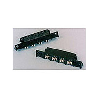
556881-2 TE Connectivity, 556881-2 Datasheet - Page 2

556881-2
Manufacturer Part Number
556881-2
Description
2PIN WIRE TO BOARD CONN
Manufacturer
TE Connectivity
Type
Powerr
Specifications of 556881-2
Gender
RCP
Body Orientation
Straight
Number Of Contacts
2POS
Number Of Ports
1Port
Number Of Terminals
1
Contact Material
Copper Alloy
Voltage Rating Max
600VAC
Mounting Style
Through Hole
Termination Method
Solder
Contact Plating
Tin
Product Height (mm)
14.43mm
Contact Gender
Socket (Female)
Number Of Positions / Contacts
2
Termination Style
Wire
Housing Material
Polyphenylene Sulfide
Product Type
Connector
Connector Type
Connector Assembly
Pcb Mounting Orientation
Vertical
Make First / Break Last
No
Pcb Mount Retention
Without
Termination Method To Pc Board
Through Hole - Solder
Pcb Mount Alignment
Without
Sealed
No
Ul File Number
E28476
Csa File Number
LR 7189
Mating Retention Type
Latching
Vde Tested
No
Contact - Rated Current (a)
35
Operating Voltage Reference
AC
Operating Voltage (vac)
600
Tail Length (mm [in])
4.9 [0.192]
Tail Orientation
In-line
Profile Height (y-axis) (mm [in])
12.70 [0.500]
Mating Retention
With
Number Of Positions
2
Centerline (mm [in])
11.18 [0.440]
Number Of Rows
1
Length (x-axis) (mm [in])
46.736 [1.840]
Width (z-axis) (mm [in])
19.30 [0.760]
Contact Base Material
Copper Alloy
Contact Type
Pin/Socket
Contact Design
Dual Beam
Contact Plating, Mating Area, Material
Tin
Contact Plating, Mating Area, Thickness (µm [?in])
3.81 [150]
Tail Plating Material
Tin
Tail Plating, Thickness (µm [?in])
2.54 [100]
Connector Style
Receptacle
Housing Color
Black
Mating Alignment
With
Mating Alignment Type
Polarization
Ul Flammability Rating
UL 94V-0
Custom Configurable
No
Rohs/elv Compliance
RoHS compliant, ELV compliant
Lead Free Solder Processes
Not relevant for lead free process
Rohs/elv Compliance History
Always was RoHS compliant
Agency/standard
UL, CSA
Ul Rating
Recognized
Ul Voltage Rating (vac)
600
Csa Certified
Yes
Operating Temperature (°c [°f])
0 – 105 [32 – 221]
Applies To
Printed Circuit Board
Pcb Thickness, Recommended (mm [in])
1.57 – 3.18 [0.062 – 0.1251]
Application Use
Wire-to-Board
Contact Transmits (typical Application)
Power
Packaging Method
Loose Piece
Lead Free Status / RoHS Status
Compliant
3.3.
3.4.
3.5.
Rev A
Examination of product.
Termination resistance.
Insulation resistance.
Dielectric withstanding voltage.
Temperature rise vs current.
Vibration, sinusoidal.
Mechanical shock, specified pulse.
Ratings
!
!
!
Performance and Test Description
Product is designed to meet the electrical, mechanical and environmental performance requirements
specified in Figure 1. Unless otherwise specified, all tests shall be performed at ambient environmental
conditions per Test Specification 109-1.
Test Requirements and Procedures Summary
Test Description
Voltage: 600 volts alternating current (rms)
Current: See Figure 4 for applicable current carrying capability
Temperature: 0 to 105° C
Meets requirements of product
drawing and Application
Specification 114-6044.
∆R 1 milliohm maximum.
5000 megohms minimum.
2200 vac at sea level.
1 minute hold with no breakdown or
flashover.
30° C maximum temperatur e rise at
specified current.
No discontinuities of 1 microsecond
or longer duration.
See Note.
No discontinuities of 1 microsecond
or longer duration.
See Note.
Figure 1 (continued)
MECHANICAL
ELECTRICAL
Requirement
Visual, dimensional and functional
per applicable quality inspection
plan.
TE Spec 109-6-1.
Subject samples to 50 mv
maximum open circuit at 100 ma
maximum.
See Figure 3.
TE Spec 109-28-4.
Test between adjacent contacts of
mated samples.
TE Spec 109-29-1.
Test between adjacent contacts of
mated samples.
TE Spec 109-45-1.
Measure temperature rise vs
current.
See Figures 4 and 5.
TE Spec 109-21-1.
Subject mated samples to 10-55-
10 Hz traversed in 1 minute with
.06 inch maximum excursion. 2
hours in each of 3 mutually
perpendicular planes.
See Figure 6.
TE Spec 109-26-1.
Subject mated samples to 50 G's
half-sine shock pulses of 11
milliseconds duration. 3 shocks in
each direction applied along 3
mutually perpendicular planes, 18
total shocks.
See Figure 6.
Procedure
108-1349
2 of 7


