556881-7 TE Connectivity, 556881-7 Datasheet

RCPT ASY,VRT,AMPINRGY WTB,7POS

556881-7

Manufacturer Part Number
556881-7
Description
RCPT ASY,VRT,AMPINRGY WTB,7POS
Manufacturer
TE Connectivity
Datasheets

Specifications of 556881-7

Voltage Rating
600 V
Number Of Positions / Contacts
7
Mounting Style
PCB
Termination Style
Solder
Contact Plating
Tin Lead
Contact Material
Copper Alloy
Product Type
Connector
Connector Type
Connector Assembly
Pcb Mounting Orientation
Vertical
Make First / Break Last
No
Pcb Mount Retention
Without
Termination Method To Pc Board
Through Hole - Solder
Pcb Mount Alignment
Without
Sealed
No
Ul File Number
E28476
Csa File Number
LR 7189
Mating Retention Type
Latching
Vde Tested
No
Contact - Rated Current (a)
35
Operating Voltage Reference
AC
Operating Voltage (vac)
600
Tail Length (mm [in])
4.9 [0.192]
Tail Orientation
In-line
Profile Height (y-axis) (mm [in])
12.70 [0.500]
Mating Retention
With
Number Of Positions
7
Centerline (mm [in])
11.18 [0.440]
Number Of Rows
1
Length (x-axis) (mm [in])
102.54 [4.040]
Width (z-axis) (mm [in])
19.30 [0.760]
Contact Base Material
Copper Alloy
Contact Type
Pin/Socket
Contact Design
Dual Beam
Contact Plating, Mating Area, Material
Tin
Contact Plating, Mating Area, Thickness (µm [?in])
3.81 [150]
Tail Plating Material
Tin
Tail Plating, Thickness (µm [?in])
2.54 [100]
Connector Style
Receptacle
Housing Material
Polyphenylene Sulfide
Housing Color
Black
Mating Alignment
With
Mating Alignment Type
Polarization
Ul Flammability Rating
UL 94V-0
Custom Configurable
No
Rohs/elv Compliance
RoHS compliant, ELV compliant
Lead Free Solder Processes
Not relevant for lead free process
Rohs/elv Compliance History
Always was RoHS compliant
Agency/standard
UL, CSA
Ul Rating
Recognized
Ul Voltage Rating (vac)
600
Csa Certified
Yes
Operating Temperature (°c [°f])
0 – 105 [32 – 221]
Applies To
Printed Circuit Board
Pcb Thickness, Recommended (mm [in])
1.57 – 3.18 [0.062 – 0.1251]
Application Use
Wire-to-Board
Contact Transmits (typical Application)
Power
Packaging Method
Loose Piece
Lead Free Status / Rohs Status
 Details
1.
1.1.
1.2.
1.3.
2.
2.1.
3.
3.1.
3.2.
©2011 Tyco Electronics Corporation,
a TE Connectivity Ltd. Company
All Rights Reserved
TE logo is a trademark.
SCOPE
Content
This specification covers the performance, tests and quality requirements for the AMPINNERGY*
wire-to-board connectors. This includes vertical and right angle receptacles assemblies, plug housings,
crimp dual beam contacts for wire-to-board application.
Qualification
When tests are performed on the subject product line, the procedures specified in Figure 1 shall be
used. All inspections shall be performed using the applicable inspection plan and product drawing.
Qualification Test Results
Successful qualification testing on the subject product line was completed on 02Dec97. The test file
numbers for this testing are CTL 3451-010-002 and CTL 3451-000-003. This documentation is on file at
and available from the Americas Regional Laboratory.
APPLICABLE DOCUMENTS
The following documents form a part of this specification to the extent specified herein. Unless
otherwise specified, the latest edition of the document applies. In the event of conflict between the
requirements of this specification and the product drawing, the product drawing shall take precedence.
In the event of conflict between the requirements of this specification and the referenced documents,
this specification shall take precedence.
TE Connectivity (TE) Documents
!
!
!
!
REQUIREMENTS
Design and Construction
Product shall be of the design, construction and physical dimensions specified on the applicable product
drawing.
Materials
!
!
109-1: General Requirements for Test Specifications
109 Series: Test Specifications as indicated in Figure 1
114-6044: Application Specification
501-406: Qualification Test Report
Contacts:
Housings:
Dual Beam: Copper alloy, tin plated
PCB: Copper, tin plated
Receptacle: Polyphthalmide, UL 94V-0
Plug: Polycarbonate, UL 94V-0
| Indicates change
*Trademark
Product
Specification
Connector, AMPINNERGY*, Wire-To-Board
For latest revision, visit our website at www.te.com/documents.
For Regional Customer Service, visit our website at www.te.com
Other products, logos, and company names might be trademarks of their respective owners.
108-1349
11Mar11 Rev A
1 of 7
LOC B

Related parts for 556881-7

556881-7 Summary of contents

Page 1

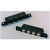
... Receptacle: Polyphthalmide, UL 94V-0 • Plug: Polycarbonate, UL 94V-0 ©2011 Tyco Electronics Corporation, | Indicates change a TE Connectivity Ltd. Company *Trademark All Rights Reserved TE logo is a trademark. For latest revision, visit our website at www.te.com/documents. For Regional Customer Service, visit our website at www.te.com Other products, logos, and company names might be trademarks of their respective owners. ...

Page 2

Ratings ! Voltage: 600 volts alternating current (rms) ! Current: See Figure 4 for applicable current carrying capability ! Temperature 105° C 3.4. Performance and Test Description Product is designed to meet the electrical, mechanical and environmental ...

Page 3

Test Description Durability. Mating force. Unmating force. Thermal shock. Humidity-temperature cycling. Temperature life. Shall meet visual requirements, show no physical damage, and meet requirements of additional NOTE tests as specified in the Product Qualification and Requalification Test Sequence shown in ...

Page 4

Product Qualification and Requalification Test Sequence Examination of product Termination resistance Insulation resistance Dielectric withstanding voltage Temperature rise vs current Vibration Mechanical shock Durability Mating force Unmating force Thermal shock Humidity-temperature cycling Temperature life (a) See paragraph 4.1.A. NOTE ...

Page 5

Acceptance Acceptance is based on verification that the product meets the requirements of Figure 1. Failures attributed to equipment, test setup or operator deficiencies shall not disqualify the product. When product failure occurs, corrective action shall be taken and ...

Page 6

Rated Current vs Ambient Temperature Rating for Single Circuit 1 .062 inch thick printed circuit board, 2 ounce copper trace, double sided, .360 inch wide trace. NOTE Percent Connector Loading Single Contact To determine acceptable current carrying capacity for the ...

Page 7

Vibration & Mechanical Shock Mounting Fixture Rev A Figure 5 Temperature Rise Measurement Points Figure 6 (Fixture 92-660368-000-1 through -004) 108-1349 ...

Related keywords